AIR CONDITIONING SYSTEM(for Automatic Air Conditioning System), Diagnostic DTC:B1434/23, B1435/-23
| DTC Code | DTC Name |
|---|---|
| B1434/23 | Open in Evaporator Sensor Circuit |
| B1435/-23 | Short in Evaporator Sensor Circuit |
DESCRIPTION
The evaporator temperature sensor (No. 1 cooler thermistor) is installed on the No. 1 cooler evaporator sub-assembly in the air conditioner unit to detect the temperature of the air that has passed through the No. 1 cooler evaporator sub-assembly and is used to control the air conditioning. It sends signals to the air conditioning control assembly. The resistance of the evaporator temperature sensor (No. 1 cooler thermistor) changes in accordance with the cooled air temperature that has passed through the No. 1 cooler evaporator sub-assembly. As the temperature decreases, the resistance increases. As the temperature increases, the resistance decreases.
The air conditioning control assembly applies voltage (5 V) to the evaporator temperature sensor (No. 1 cooler thermistor) and reads voltage changes as the resistance of the evaporator temperature sensor (No. 1 cooler thermistor) changes. This sensor is used for frost prevention.
| DTC No. | DTC Detection Condition | Trouble Area |
|---|---|---|
| B1434/23 | Open in evaporator sensor circuit |
|
| B1435/-23 | Short in evaporator sensor circuit |
|
WIRING DIAGRAM
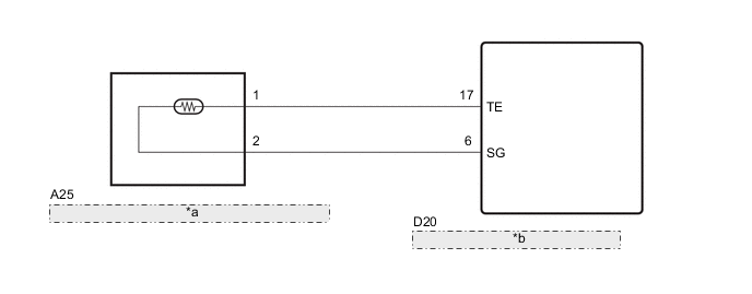
| *a | EVAPORATOR TEMPERATURE SENSOR (NO. 1 COOLER THEMISTOR) |
| *b | AIR CONDITIONING CONTROL ASSEMBLY |
PROCEDURE
-
READ VALUE USING GTS
-
Connect the GTS to the DLC3.
-
Turn the ignition switch to ON.
-
Turn the GTS on.
-
Enter the following menus: Body Electrical / Air Conditioner / Data List.
-
Check the value(s) by referring to the table below.
Air Conditioner Tester Display Measurement Item/Range Normal Condition Diagnostic Note Evaporator Temp Sensor
(Evap Temp)
Evaporator temperature sensor (No. 1 cooler thermistor) /
Min.: -82.48°C (-116.46°F)
Max.: 153.55°C (308.39°F)
Actual evaporator temperature displayed - OK The display is as specified in the normal condition column. Result Result Proceed to OK (When troubleshooting according to the DTC) A OK (When troubleshooting according to Problem Symptoms Table) B NG C
B 
PROCEED TO NEXT SUSPECTED AREA SHOWN IN PROBLEM SYMPTOMS TABLE Click here
C 
INSPECT EVAPORATOR TEMPERATURE SENSOR (NO. 1 COOLER THERMISTOR) Click here
A 
-
-
CHECK FOR DTC
-
Clear the DTCs Click here
-
Check the DTCs Click here
OK DTC is not output.
OK
END
NG
REPLACE AIR CONDITIONING CONTROL ASSEMBLY Click here
-
-
INSPECT EVAPORATOR TEMPERATURE SENSOR (NO. 1 COOLER THERMISTOR)
-
Remove the evaporator temperature sensor (No. 1 cooler thermistor) Click here.
-
Inspect the evaporator temperature sensor (No. 1 cooler thermistor) Click here
NG
REPLACE EVAPORATOR TEMPERATURE SENSOR (NO. 1 COOLER THERMISTOR) Click here
OK
-
-
CHECK HARNESS AND CONNECTOR (EVAPORATOR TEMPERATURE SENSOR (NO. 1 COOLER THERMISTOR) - AIR CONDITIONING CONTROL ASSEMBLY)
-
Disconnect the D20 air conditioning control assembly.
-
Measure the resistance according to the value(s) in the table below.
Standard Resistance Tester Connection Condition Specified Condition A25-1 - D20-17(TE) Always Below 1 Ω A25-2 - D20-6(SG) Always Below 1 Ω A25-1 - Body ground Always 10 kΩ or higher A25-2 - Body ground Always 10 kΩ or higher
OK
REPLACE AIR CONDITIONING CONTROL ASSEMBLY Click here
NG
REPAIR OR REPLACE HARNESS OR CONNECTOR
-