AIR CONDITIONING SYSTEM(for Automatic Air Conditioning System), Diagnostic DTC:B1432/22, B1433/-22
| DTC Code | DTC Name |
|---|---|
| B1432/22 | Open in Ambient Temperature Sensor Circuit |
| B1433/-22 | Short in Ambient Temperature Sensor Circuit |
DESCRIPTION
The thermistor assembly is installed in the front part of the condenser to detect the ambient temperature and control the air conditioner. The thermistor assembly is connected to the combination meter assembly and detects fluctuations in the ambient temperature. This data is used for controlling the room temperature. The thermistor assembly sends a signal to the air conditioning control assembly via the combination meter assembly. The resistance of the thermistor assembly changes in accordance with the ambient temperature. As the temperature decreases, the resistance increases. As the temperature increases, the resistance decreases.
The combination meter assembly applies a voltage (5 V) to the thermistor assembly and reads voltage changes as changes in the resistance of the thermistor assembly. The combination meter assembly sends the read signal to the air conditioning control assembly via CAN communication.
| DTC No. | DTC Detection Condition | Trouble Area |
|---|---|---|
| B1432/22 | Open in ambient temperature sensor circuit |
|
| B1433/-22 | Short in ambient temperature Sensor circuit |
|
WIRING DIAGRAM
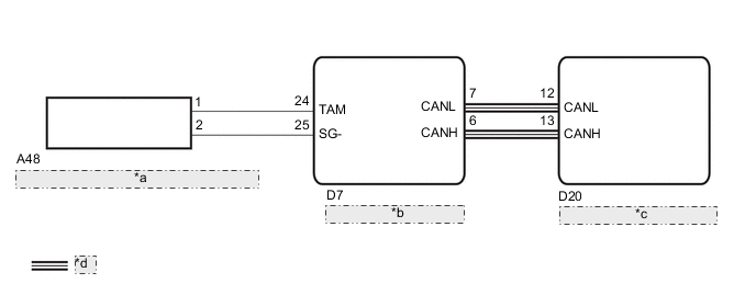
| *a | AMBIENT TEMPERATURE SENSOR (THERMISTOR ASSEMBLY) |
| *b | COMBINATION METER ASSEMBLY |
| *c | AIR CONDITIONING CONTROL ASSEMBLY |
| *d | CAN Communication Line |
CAUTION / NOTICE / HINT
Note
-
The heater and air conditioning system uses the CAN communication system. First, carry out the check of CAN communication system in accordance with the "HOW TO PROCEED WITH TROUBLESHOOTING", and confirm that there are no problems with the communications system before proceeding with troubleshooting.
-
Errors with the combination meter assembly may affect this DTC. Prior to carrying out an inspection, inspect "Meter and gauge system" DTCs, and confirm that the combination meter assembly is normal.
PROCEDURE
-
READ VALUE USING GTS
-
Connect the GTS to the DLC3.
-
Turn the ignition switch to ON.
-
Turn the GTS on.
-
Enter the following menus: Body Electrical / Air Conditioner / Data List.
-
Check the value(s) by referring to the table below.
Air Conditioner Tester Display Measurement Item/Range Normal Condition Diagnostic Note Ambient Temp Sensor
(Ambi Temp Sens)
Ambient temperature sensor (thermistor assembly) /
Min: -40.00°C (-40.00°F)
Max: 80.00°C (176.00°F)
Actual ambient temperature displayed - OK The display is as specified in the normal condition column. Result Result Proceed to OK (When troubleshooting according to the DTC) A OK (When troubleshooting according to Problem Symptoms Table) B NG C
B 
PROCEED TO NEXT SUSPECTED AREA SHOWN IN PROBLEM SYMPTOMS TABLE Click here
C 
INSPECT AMBIENT TEMPERATURE SENSOR (THERMISTOR ASSEMBLY) Click here
A 
-
-
CHECK FOR DTC
-
Clear the DTCs Click here
-
Check the DTCs Click here
OK DTC is not output.
OK
END
NG
REPLACE AIR CONDITIONING CONTROL ASSEMBLY Click here
-
-
INSPECT AMBIENT TEMPERATURE SENSOR (THERMISTOR ASSEMBLY)
-
Remove the ambient temperature sensor (thermistor assembly) Click here.
-
Inspect the ambient temperature sensor (thermistor assembly) Click here.
NG
REPLACE AMBIENT TEMPERATURE SENSOR (THERMISTOR ASSEMBLY) Click here
OK
-
-
CHECK HARNESS AND CONNECTOR (AMBIENT TEMPERATURE SENSOR (THERMISTOR ASSEMBLY) - COMBINATION METER ASSEMBLY)
-
Disconnect the D7 conditioning meter assembly connector.
-
Measure the resistance according to the value(s) in the table below.
Standard Resistance Tester Connection Condition Specified Condition A48-1 - D7-24(TAM) Always Below 1 Ω A48-2 - D7-25(SG-) Always Below 1 Ω A48-1 - Body ground Always 10 kΩ or higher A48-2 - Body ground Always 10 kΩ or higher
OK
REPLACE AIR CONDITIONING CONTROL ASSEMBLY Click here
NG
REPAIR OR REPLACE HARNESS OR CONNECTOR
-