AIR CONDITIONING SYSTEM(for Automatic Air Conditioning System) SYSTEM DESCRIPTION
-
GENERAL
-
The air conditioning system has the following controls.
Control Outline Outlet Air Temperature Control In compliance with the temperature set at the temperature control dial, the air conditioning control assembly (air conditioning ECU) calculates the outlet temperature based on the input signals from various sensors. In addition, corrections in accordance with the signals from the evaporator temperature sensor (No. 1 cooler thermistor) and E.F.I. engine coolant temperature sensor are added to control the outlet air temperature. The temperature setting for the driver and front passenger is controlled independently in order to provide a separate vehicle interior temperature for the right and left side of the vehicle. Thus, air conditioning control that accommodates occupant preferences has been realized. Blower Control Controls the blower motor with fan sub-assembly in accordance with the airflow volume that has been calculated by the air conditioning control assembly (air conditioning ECU) based on the input signals from various sensors. Air Inlet Control Automatically controls the air inlet control damper in accordance with the outlet temperature that has been calculated by the air conditioning control assembly (air conditioning ECU). Drives the servo motor (for air inlet) according to the operation of the air inlet control switch and moves the dampers to the FRESH or RECIRC position.
-
-
MODE POSITION AND DAMPER OPERATION
-
Mode Position and Damper Operation
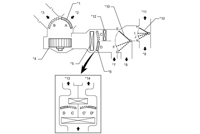
Text in Illustration *1 Air Inlet Control Door *2 Recirculated Air *3 Fresh Air *4 Blower Motor with Fan Sub-assembly *5 No.1 Cooler Evaporator Sub-assembly *6 Air Mix Control Door *7 Side Register *8 Center Register *9 Footwell Register Duct *10 Mode Control Door *11 Front Defroster, Side Defroster *12 Heater Radiator Unit Sub-assembly *13 Passenger Side *14 Driver Side Functions of Main Dampers Control Damper Operation Position Damper Position Operation Air Inlet Control Damper FRESH A Brings in fresh air. RECIRCULATION B Recirculates internal air. Air Mix Control Damper MAX COLD to MAX HOT Temperature Setting C - D
(C' - D')
Varies the mixture ratio of warm air and cool air in order to regulate the temperature continuously between hot and cold. Mode Control Damper 
FACE E, H, Air blows out of the center register and side register ducts. 
BI-LEVEL F, H Air blows out of the center register side register and footwell register ducts. 
FOOT G, I Air blows out of the footwell register and side registers ducts. In addition, air blows out slightly from the front defroster and side defrosters. 
FOOT AND DEFROSTER G, J Defrosts the windshield through the front defroster, side defroster, and side registers ducts., while air is also blown out from the footwell register ducts. 
DEFROSTER G, K Defrosts the windshield through the front defroster, side defrosters, and side registers ducts.
-
-
AIR OUTLETS AND AIRFLOW VOLUME
-
Air Outlets and Airflow Volume
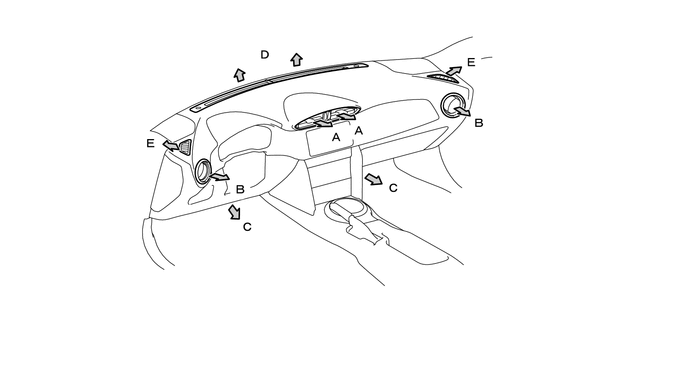
Indication Mode FACE Footwell Defroster CTR SIDE FRONT SIDE A B C D E FACE 

BI-LEVEL 
FOOT 

FOOT AND DEFROSTER DEFROSTER
-
The size of each circle ○ indicates the ratio of airflow volume.
-
-
-
COMPRESSOR
-
General:
-
A compact and high performance scroll compressor with has been adopted.
-
The scroll compressor with oil separator consists of a spirally wound fixed scroll and rotating scroll that from a pair, and oil separator, and a magnetic clutch.
The fixed scroll is integrated with the housing. Because the rotation of the shaft causes the rotating scroll to revolve while maintaining the same posture, the volume of the space that is partitioned by both scrolls varies to perform the suction, compression, and the discharge of the refrigerant gas.
A pin is attached behind the rotating scroll to prevent the autorotation of the rotating scroll, allowing it only to revolve.
Locating the suction port directly above the scrolls enables direct suction, thus realizing improved suction efficiency.
Containing a built-in oil separator, this compressor is able to separate the compressor oil that is intermixed with the refrigerant and circulates in the refrigeration cycle, thus realizing a reduction in the oil circulation rate.
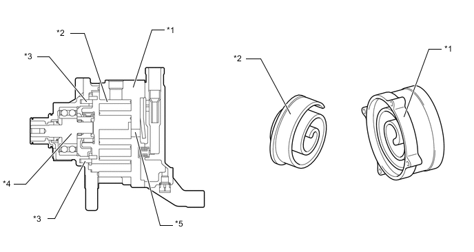
Text in Illustration *1 Fixed Scroll *2 Rotating Scroll *3 Pins *4 Shaft *5 Discharge Port - - -
A CS (Centrifugal with Shutter) type oil separator has been adopted to reduce the circulation rate of the compressor oil that is intermixed with the refrigerant and circulates in the refrigeration cycle.
This oil separator is provided with a cylindrical pipe in the separator case, enabling the refrigerant gas that has been discharged through the discharge gas inlet to be separated into refrigerant gas and oil through centrifugal force, and minimizing the outflow of the oil to the discharge service port. As a result, the oil circulation rate has been reduced and makes energy savings possible.
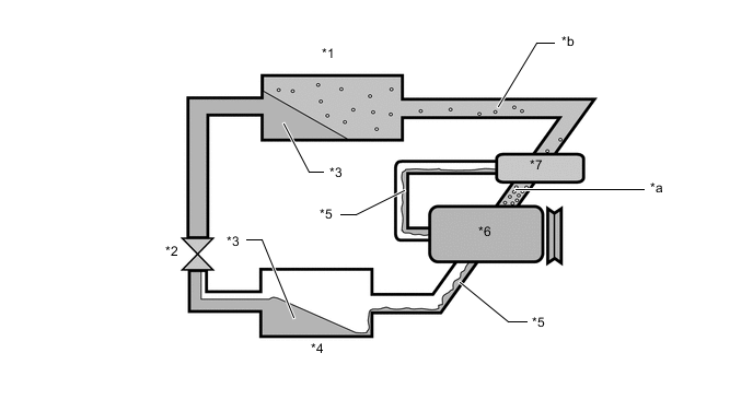
Text in Illustration *1 Cooler Condenser Assembly and Modulator *2 Cooler Expansion Valve *3 Refrigerant Gas + Compressor Oil *4 No.1 Cooler Evaporator Sub-assembly *5 Oil *6 Compressor Assembly *7 Oil Separator - - *a Oil Circulation Ratio of 4% *b Oil Circulation Ratio of 1%
-
-
Compressor Operation
-
As the capacity of the compression chamber, which is created between the rotating scroll and the fixed scroll, increases in accordance with the revolution of the rotating scroll, refrigerant gas is drawn in from the intake port.
-
From the state at which the suction process has been completed, as the revolution of the rotating scroll advances further, the capacity of the compression chamber decreases gradually. Consequently, the refrigerant gas that has been drawn in becomes compressed gradually and is sent to the center of the fixed scroll. The compression of the refrigerant gas is completed when the rotating scroll completes approximately 2 revolutions.
-
When the compression of the refrigerant gas is completed and the refrigerant pressure becomes high, the refrigerant gas discharges through the discharge port located in the center of the fixed scroll by pushing the discharge valve.
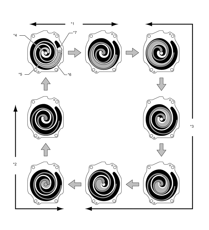
Text in Illustration *1 Suction *2 Discharge *3 Compression *4 Discharge Port *5 Rotating Scroll *6 Fixed Scroll *7 Intake port - - -
The refrigerant gas that is discharged from the discharge port flows by rotating around the cylindrical pipe in the oil separator. At this time, the centrifugal force that is created during the rotation separates the refrigerant gas and the compressor oil due to the difference in their specific gravity. The refrigerant gas with the lighter specific gravity passes through the inside of the pipe and travels from the discharge service port to the outside of the compressor. The compressor oil with the heavier specific gravity is discharged through the oil discharge hole in the shutter and is stored in the oil storage chamber. Then, the compressor oil is fed again into the compressor and circulates inside the compressor.
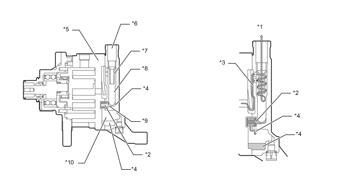
Text in Illustration *1 Refrigerant *2 Shutter *3 Refrigerant and Compressor Oil *4 Compressor Oil *5 Valve Chamber D *6 Service Port *7 Pipe *8 Case *9 Oil Discharge Hole *10 Oil Storage Chamber
-
-
-
EVAPORATOR TEMPERATURE SENSOR (NO. 1 COOLER THERMISTOR)
The evaporator temperature sensor (No. 1 cooler thermistor) detects the temperature of the cooled air immediately past the evaporator in the form of resistance changes, and outputs this data to the air conditioning control assembly.
-
BLOWER MOTOR CONTROL
The blower motor control has internal circuitry that uses electrical current to change the signal from the air conditioning control assembly (air conditioning ECU) and to change the speed of the blower motor with fan sub-assembly.
-
SERVO MOTOR
-
A No. 1 air conditioning radiator damper servo sub-assembly, No. 3 air conditioning radiator damper servo sub-assembly, No. 4 air conditioning radiator damper servo sub-assembly, and No. 5 air conditioning radiator damper servo sub-assembly have been adopted.
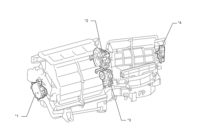
Text in Illustration *1 No. 5 Air Conditioning Radiator Damper Servo Sub-assembly *2 No. 3 Air Conditioning Radiator Damper Servo Sub-assembly *3 No. 4 Air Conditioning Radiator Damper Servo Sub-assembly *4 No. 1 Air Conditioning Radiator Damper Servo Sub-assembly -
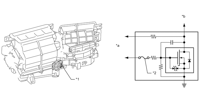
The No. 1 air conditioning radiator damper servo sub-assembly receives an activation signal from the air conditioning control panel for its internal/fresh air select switch, whereupon it causes motor rotation and opens or closes the internal/fresh air door through a link.
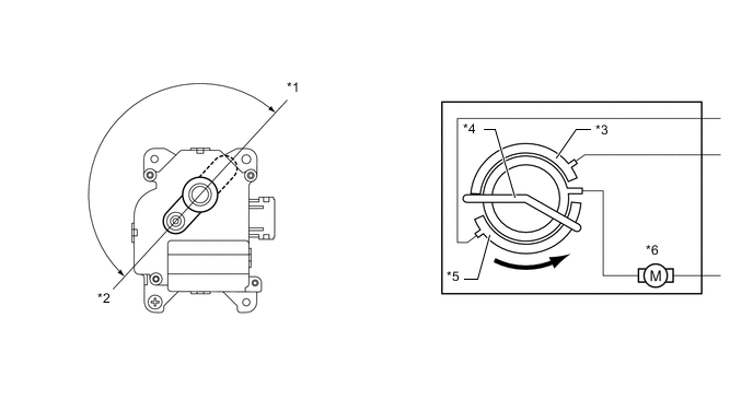
Text in Illustration *1 Recirculated Air *2 Fresh Air *3 Internal air contact *4 Moving contact *5 Fresh air contact *6 Motor -
In the No. 3 air conditioning radiator damper servo sub-assembly, the air conditioning control assembly (air conditioning ECU) causes the servo motor to rotate to a particular position due to action taken to change the mode of the air conditioning control assembly or by automaticcontrol, causing the mode door to open or close through a link.
-
The actual position of the mode door is measured by a potentiometer installed in the No. 3 air conditioning radiator damper servo sub-assembly, and the change in resistance caused by the change in door position is fed back into the air conditioning control assembly (air conditioning ECU) as a change in voltage.
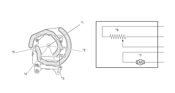
Text in Illustration *1 DEF *2 F/D *3 FOOT *4 B/L *5 FACE *6 Potentiometer *7 Motor - - -
In the No. 4 air conditioning radiator damper servo sub-assembly and No. 5air conditioning radiator damper servo sub-assembly, the air conditioning control assembly (air conditioning ECU) causes the servo motor to rotate to a particular position due to action taken to set the temperature or by automatic control, causing the air mix door to open or close through a link.
-
The actual position of the air mix door is measured by a potentiometer installed in the No. 4 air conditioning radiator damper servo sub-assembly and No. 5air conditioning radiator damper servo sub-assembly, and the change in resistance caused by the change in door position is fed back into the air conditioning control assembly (air conditioning ECU) as a change in voltage.
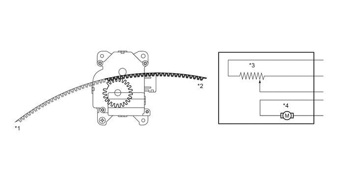
Text in Illustration *1 Max Cool *2 Max Hot *3 Potentiometer *4 Motor
-
-
COOLER (ROOM TEMP. SENSOR THERMISTOR)
The cooler (room temp. sensor) thermistor detects the room temperature based on changes in the resistance of its built-in thermistor.
-
AMBIENT TEMPERATURE SENSOR (THERMISTOR ASSEMBLY)
The thermistor assembly detects the ambient temperature based on changes in the resistance of its built-in thermistor. This signal is used by the air conditioning control assembly (air conditioning ECU).
-
AUTOMATIC LIGHT CONTROL SENSOR
-
A single-unit light sensor has been adopted for the automatic light control sensor, reducing the part count.
-
Changes in the amount of light are detected by the scanner (integrated optical sensor) and output to the air conditioning control assembly (air conditioning ECU).
-
-
AIR CONDITIONING PRESSURE SWITCH
The air conditioning pressure switch (airconditioner tube assembly) uses refrigerant pressure to output an on/off signal to the ECM to control the compressor with magnet clutch.