AIR CONDITIONING UNIT INSTALLATION
PROCEDURE
-
INSTALL AIR CONDITIONING UNIT ASSEMBLY (for Automatic Air Conditioning System)
-
Install the 3 bolts and 3 nuts.
- Torque:
- 7.5 N*m { 76 kgf*cm, 66 in.*lbf }
-
Engage the drain cooler hose.
-
Connect each connector and engage each clamp and install the air conditioning unit assembly.
-
-
INSTALL AIR CONDITIONING UNIT ASSEMBLY (for Manual Air Conditioning System)
Tech Tips
Use the same procedure as for the automatic air conditioning system.
-
INSTALL AIR CONDITIONING UNIT ASSEMBLY (w/o Air Conditioning System)
Tech Tips
Use the same procedure as for the automatic air conditioning system.
-
INSTALL INSTRUMENT PANEL REINFORCEMENT ASSEMBLY
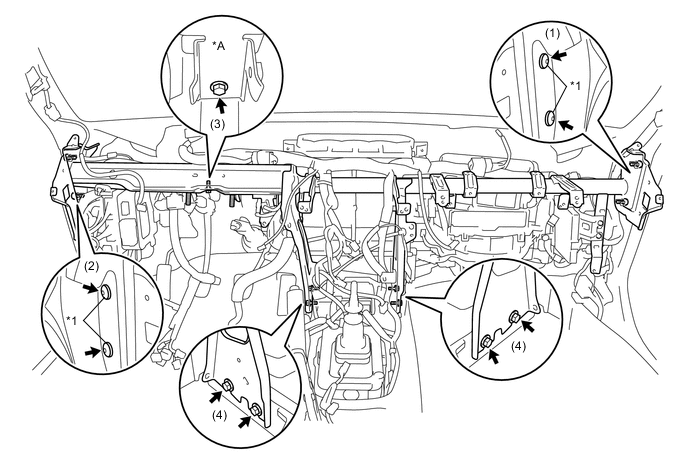
Text in Illustration *A for RHD - - *1 "TORX" Bolt - -
-
Using a 4 mm "TORX" wrench, install the 4 "TORX" Bolts in the order shown in the illustration.
- Torque:
- 25 N*m { 255 kgf*cm, 18 ft.*lbf }
-
Install the instrument panel reinforcement assembly with the 5 bolts in the order shown in the illustration.
- Torque:
- 25 N*m { 255 kgf*cm, 18 ft.*lbf }
-
Connect each connector and engage each clamp.
-
Connect the 2 earth wires with the 2 bolts.
-
-
INSTALL COWL SIDE TRIM BOARD LH
-
INSTALL COWL SIDE TRIM BOARD RH
-
INSTALL FRONT DOOR SCUFF PLATE LH
-
INSTALL FRONT DOOR SCUFF PLATE RH
-
INSTALL STEERING COLUMN ASSEMBLY
-
INSTALL LOWER NO. 1 INSTRUMENT PANEL AIR BAG ASSEMBLY (w/ Knee Airbag)
-
INSTALL INSTRUMENT PANEL SUB-ASSEMBLY
-
CONNECT AIR CONDITIONER TUBE AND ACCESSORY ASSEMBLY
-
Remove the vinyl tape from the pipe.
-
Sufficiently apply compressor oil to a new O-ring and fitting surface of the air conditioner tube and accessory assembly.
Compressor oil for HFC-134a (R134a) ND-OIL 8 or equivalent for HFO-1234yf (R1234yf) ND-OIL 12 or equivalent -
Install the O-ring to the air conditioner tube and accessory assembly.
-
Install the air conditioner tube and accessory assembly.
-
-
CONNECT SUCTION HOSE SUB-ASSEMBLY
-
Remove the vinyl tape from the pipe.
-
Sufficiently apply compressor oil to a new O-ring and the fitting surface of the suction hose sub-assembly.
Compressor oil for HFC-134a (R134a) ND-OIL 8 or equivalent for HFO-1234yf (R1234yf) ND-OIL 12 or equivalent -
Connect the O-ring to the suction hose sub-assembly.
-
Connect the suction hose sub-assembly.
-
Rotate the hook connector in the direction indicated by the arrow in the illustration.
-
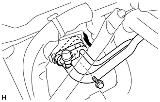
Insert the pipe joint into the cooler expansion valve securely and tighten the bolt.
- Torque:
- 7.5 N*m { 76 kgf*cm, 66 in.*lbf }
-
-
CONNECT OUTLET HEATER WATER HOSE A
-
Install the outlet heater water hose A and attach the clip.
Tech Tips
Install the outlet heater water hose A while aligning it with the matching marks made when it was removed.
-
-
CONNECT INLET HEATER WATER HOSE A
-
Install the inlet heater water hose A and attach the clip.
Tech Tips
Install the inlet heater water hose A while aligning it with the matching marks made when it was removed.
-
-
CONNECT CABLE TO NEGATIVE BATTERY TERMINAL
- Torque:
- 6.0 N*m { 61 kgf*cm, 53 in.*lbf }
-
ADD ENGINE COOLANT
-
CHARGE AIR CONDITIONING SYSTEM WITH REFRIGERANT
-
for HFC-134a (R134a):
-
for HFO-1234yf (R1234yf):
-
-
INSPECT FOR COOLANT LEAK
-
WARM UP ENGINE
-
for HFC-134a (R134a):
-
for HFO-1234yf (R1234yf):
-
-
INSPECT FOR REFRIGERANT LEAK
-
for HFC-134a (R134a):
-
for HFO-1234yf (R1234yf):
-
-
INSPECT SRS WARNING LIGHT