AIRBAG SYSTEM, Diagnostic DTC:B1678, B1679

| DTC Code | DTC Name |
|---|---|
| B1678 | Lost Communication with Rear Floor Airbag Sensor LH |
| B1679 | Rear Floor Airbag Sensor LH Initialization Incomplete |
DESCRIPTION
-
The No. 2 airbag sensor assembly circuit consists of the airbag ECU assembly and No. 2 airbag sensor assembly.
-
The No. 2 airbag sensor assembly detects impacts to the vehicle and sends signals to the airbag ECU assembly to determine if the airbag should be deployed.
-
These DTCs are stored when a malfunction is detected in the No. 2 airbag sensor assembly circuit.
| DTC Code | DTC Detection Condition | Trouble Area |
|---|---|---|
| B1678 B1679 |
|
|
WIRING DIAGRAM
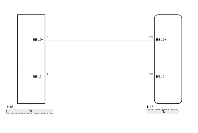
| *a | No. 2 Airbag Sensor Assembly |
| *b | Airbag ECU Assembly |
CAUTION / NOTICE / HINT
Note
After turning the ignition switch off, waiting time may be required before disconnecting the cable from the negative (-) battery terminal. Therefore, make sure to read the disconnecting the cable from the negative (-) battery terminal notices before proceeding with work Click here.
PROCEDURE
-
CHECK CONNECTORS
-
Turn the ignition switch off.
-
Disconnect the cable from the negative (-) battery terminal.
CAUTION:
Wait at least 90 seconds after disconnecting the cable from the negative (-) battery terminal to disable the SRS system.
-
Check that the connectors are properly connected to the airbag ECU assembly and No. 2 airbag sensor assembly.
OK The connectors are properly connected. Tech Tips
If the connectors are not connected securely, reconnect the connectors and proceed to the next inspection.
-
Disconnect the connectors from the airbag ECU assembly and No. 2 airbag sensor assembly.
-
Check that the terminals of connectors are not damaged.
OK The connectors are not deformed or damaged.
NG 
REPLACE FLOOR WIRE
OK 
-
-
CHECK FLOOR WIRE (OPEN)
-
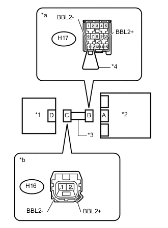
Text in Illustration *1 No. 2 Airbag Sensor Assembly *2 Airbag ECU Assembly *3 Floor Wire *4 Service Wire *a Front view of wire harness connector
(to Airbag ECU Assembly)
*b Front view of wire harness connector
(to No. 2 Airbag Sensor Assembly)
Using a service wire, connect terminals 11 (BBL2+) and 12 (BBL2-) of connector B.
Note
Do not forcibly insert the service wire into the terminals of the connector when connecting the wire.
-
Measure the resistance according to the value(s) in the table below.
Standard Resistance Tester Connection Condition Specified Condition H16-1 (BBL2-) - H16-2 (BBL2+) Always Below 1 Ω -
Disconnect the service wire from connector B.
NG
REPLACE FLOOR WIRE
OK
-
-
CHECK FLOOR WIRE (SHORT)
-
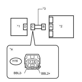
Text in Illustration *1 No. 2 Airbag Sensor Assembly *2 Airbag ECU Assembly *3 Floor Wire *a Front view of wire harness connector
(to No. 2 Airbag Sensor Assembly)
Measure the resistance according to the value(s) in the table below.
Standard Resistance Tester Connection Condition Specified Condition H16-1 (BBL2-) - H16-2 (BBL2+) Always 1 MΩ or higher
NG
REPLACE FLOOR WIRE
OK
-
-
CHECK FLOOR WIRE (SHORT TO B+)
-
Text in Illustration *1 No. 2 Airbag Sensor Assembly *2 Airbag ECU Assembly *3 Floor Wire *a Front view of wire harness connector
(to No. 2 Airbag Sensor Assembly)
Connect the cable to the negative (-) battery terminal.
-
Turn the ignition switch to ON.
-
Measure the voltage according to the value(s) in the table below.
Standard Voltage Tester Connection Condition Specified Condition H16-1 (BBL2-) - Body ground Ignition switch ON Below 1 V H16-2 (BBL2+) - Body ground Ignition switch ON Below 1 V -
Turn the ignition switch off.
-
Disconnect the cable from the negative (-) battery terminal.
CAUTION:
Wait at least 90 seconds after disconnecting the cable from the negative (-) battery terminal to disable the SRS system.
NG
REPLACE FLOOR WIRE
OK
-
-
CHECK FLOOR WIRE (SHORT TO GROUND)
-
Text in Illustration *1 No. 2 Airbag Sensor Assembly *2 Airbag ECU Assembly *3 Floor Wire *a Front view of wire harness connector
(to No. 2 Airbag Sensor Assembly)
Measure the resistance according to the value(s) in the table below.
Standard Resistance Tester Connection Condition Specified Condition H16-1 (BBL2-) - Body ground Always 1 MΩ or higher H16-2 (BBL2+) - Body ground Always 1 MΩ or higher
NG
REPLACE FLOOR WIRE
OK
-
-
CHECK NO. 2 AIRBAG SENSOR ASSEMBLY
-
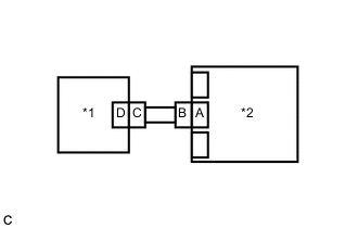
Text in Illustration *1 No. 2 Airbag Sensor Assembly *2 Airbag ECU Assembly Connect the connectors to the No. 2 airbag sensor assembly and airbag ECU assembly.
-
Replace the No. 2 airbag sensor assembly with a new one.
-
Connect the cable to the negative (-) battery terminal.
-
Clear the DTCs stored in memory Click here.
-
Turn the ignition switch off.
-
Turn the ignition switch to ON, and wait for at least 60 seconds.
-
Check for DTCs Click here.
Result Proceed to DTCs B1678 and B1679 are not output. A DTC B1678 or B1679 is output. B Tech Tips
Codes other than DTCs B1678 and B1679 may be output at this time, but they are not related to this check.
A
END (NO. 2 AIRBAG SENSOR ASSEMBLY WAS DEFECTIVE)
B
REPLACE AIRBAG ECU ASSEMBLY Click here
-