METER / GAUGE SYSTEM Operating Light Control Rheostat does not Change Light Brightness
DESCRIPTION
The brightness of the combination meter assembly is controlled by rotating the light control rheostat knob in upward and downward.
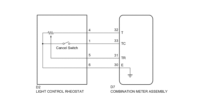
WIRING DIAGRAM
PROCEDURE
-
READ VALUE USING GTS (RHEOSTAT SWITCH)
-
Connect the GTS to the DLC3.
-
Turn the ignition switch to ON.
-
Turn the GTS on.
-
Enter the following menus: Body Electrical / Combination Meter / Data List.
-
According to the display on the tester, read the Data List.
Combination Meter Tester Display Measurement Item/Range Normal Condition Diagnostic Note Tail Cancel SW Light control rheostat switch (cancel switch) / OFF or ON OFF: Light control rheostat switch (cancel switch) → OFF - ON: Light control rheostat switch (cancel switch) → TAIL Rheostat value Light control rheostat switch input /
Min.: 0
Max.: 100
Displays rheostat volume figure
0 to 100
- OK The value displayed on the GTS changes in accordance with the actual rheostat switch operation.
OK 
REPLACE COMBINATION METER ASSEMBLY Click here
NG 
-
-
INSPECT LIGHT CONTROL RHEOSTAT
-
Remove the light control rheostat Click here.
-
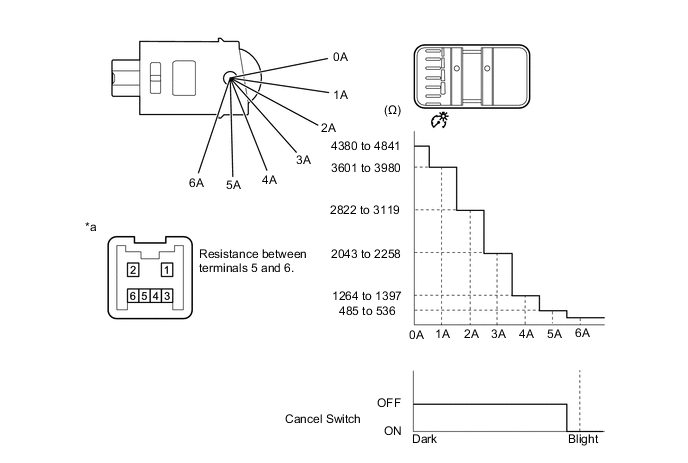
Measure the resistance according to the value(s) in the table below.
Standard Resistance Tester Connection Switch Condition Specified Condition 1 - 6 Cancel switch off → on 10 kΩ or higher → Below 1 Ω 4 - 6 Always 4475 to 4946 Ω 5 - 6 Light control rheostat fully up → Light control rheostat fully down 485 to 536 Ω → 4380 to 4841 Ω Text in Illustration *a Component without harness connected
(Light Control Rheostat)
NG
REPLACE LIGHT CONTROL RHEOSTAT Click here
OK
-
-
CHECK HARNESS AND CONNECTOR (COMBINATION METER ASSEMBLY - LIGHT CONTROL RHEOSTAT)
-
Disconnect the D7 combination meter assembly connector.
-
Disconnect the D2 light control rheostat connector.
-
Measure the resistance according to the value(s) in the table below.
Standard Resistance (Check for Open) Tester Connection Condition Specified Condition D7-30 (E) - D2-6 Always Below 1 Ω D7-31 (TR) - D2-5 Always Below 1 Ω D7-32 (T) - D2-4 Always Below 1 Ω D7-33 (TC) - D2-1 Always Below 1 Ω Standard Resistance (Check for Short) Tester Connection Condition Specified Condition D7-30 (E) or D2-6 - Body ground Always 10 kΩ or higher D7-31 (TR) or D2-5 - Body ground Always 10 kΩ or higher D7-32 (T) or D2-4 - Body ground Always 10 kΩ or higher D7-33 (TC) or D2-1 - Body ground Always 10 kΩ or higher
OK
REPLACE COMBINATION METER ASSEMBLY Click here
NG
REPAIR OR REPLACE HARNESS OR CONNECTOR
-