METER / GAUGE SYSTEM Odo/Trip Switch Malfunction
DESCRIPTION
The ODO/TRIP display of the combination meter changes each time the trip switch is pressed.
Tech Tips
For more information about switching between displays, refer to the owner's manual.
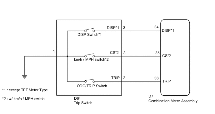
WIRING DIAGRAM
PROCEDURE
-
READ VALUE USING GTS (MULTI DISPLAY SELECT SWITCH, ODO/TRIP CHANGE SW)
-
Connect the GTS to the DLC3.
-
Turn the ignition switch to ON.
-
Turn the GTS on.
-
Enter the following menus: Body Electrical / Combination Meter / Data List.
-
According to the display on the tester, read the Data List.
Combination Meter Tester Display Measurement Item/Range Normal Condition Diagnostic Note ODO/TRIP Change SW ODO/TRIP switch / OFF or ON OFF: ODO/TRIP switch not pushed - ON: ODO/TRIP switch pushed Multi Display Select Switch Multi Display Select Switch / OFF or ON OFF: DISP switch not pushed - ON: DISP switch pushed OK The value displayed on the GTS changes in accordance with the actual ODO/TRIP change switch and multi display select switch operation.
OK 
REPLACE COMBINATION METER ASSEMBLY Click here
NG 
-
-
INSPECT TRIP SWITCH
-
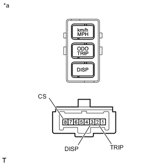
Text in Illustration *a Component without harness connected
(Trip Switch)
Remove the trip switch Click here.
-
Measure the resistance according to the value(s) in the table below.
Standard Resistance Tester Connection Switch Condition Specified Condition 2 (TRIP) - 1 ODO/TRIP switch on
(pushed)
Below 1 Ω 2 (TRIP) - 1 ODO/TRIP switch off
(not pushed)
10 kΩ or higher 3 (DISP) - 1*1 DISP switch on
(pushed)
Below 1 Ω 3 (DISP) - 1*1 DISP switch off
(not pushed)
10 kΩ or higher 8 (CS) - 1*2 km/h/MPH switch on
(pushed)
Below 1 Ω 8 (CS) - 1*2 km/h/MPH switch off
(not pushed)
10 kΩ or higher *1: except TFT Meter Type
*2 : w/ km/h / MPH Switch
NG
REPLACE TRIP SWITCH Click here
OK
-
-
CHECK HARNESS AND CONNECTOR (COMBINATION METER - TRIP SWITCH AND BODY GROUND)
-
Disconnect the D7 combination meter assembly connector.
-
Disconnect the D64 trip switch connector.
-
Measure the resistance according to the value(s) in the table below.
Standard Resistance (Check for Open) Tester Connection Condition Specified Condition D7-34 (DISP) - D64-3 (DISP)*1 Always Below 1 Ω D7-35 (CS) - D64-8 (CS)*2 Always Below 1 Ω D7-36 (TRIP) - D64-2 (TRIP) Always Below 1 Ω Standard Resistance (Check for Short) Tester Connection Condition Specified Condition D7-34 (DISP) or D64-3 (DISP) - Body ground*1 Always 10 kΩ or higher D7-35 (CS) or D64-8 (CS) - Body ground*2 Always 10 kΩ or higher D7-36 (TRIP) or D64-2 (TRIP) - Body ground Always 10 kΩ or higher *1: except TFT Meter Type
*2 : w/ km/h / MPH Switch
OK
REPLACE COMBINATION METER ASSEMBLY Click here
NG
REPAIR OR REPLACE HARNESS OR CONNECTOR
-