METER / GAUGE SYSTEM Engine Coolant Temperature Receiver Gauge Malfunction
DESCRIPTION
The combination meter assembly controls the engine coolant temperature receiver gauge in accordance with the engine coolant temperature sensor signals from the ECM through the CAN communication system.
WIRING DIAGRAM
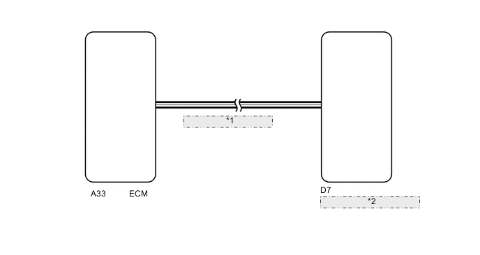
| *1 | CAN Communication Line |
| *2 | Combination Meter Assembly |
PROCEDURE
-
CHECK FOR DTC (METER / GAUGE SYSTEM)
-
Check if meter / gauge system DTCs are output Click here.
OK DTCs are not output.
MG 
GO TO DIAGNOSTIC TROUBLE CODE CHART Click here
A 
-
-
CHECK FOR DTC (SFI SYSTEM)
-
Check if the SFI system DTCs are output Click here.
OK DTCs are not output.
NG
GO TO SFI SYSTEM Click here
OK
-
-
PERFORM ACTIVE TEST USING GTS (WATER TEMPERATURE METER OPERATION)
-
Connect the GTS to the DLC3.
-
Turn the ignition switch to ON.
-
Turn the GTS on.
-
Enter the following menus: Body Electrical / Combination Meter / Active Test.
-
According to the display on the tester, perform the Active Test.
Combination Meter Tester Display Test Part Control Range Diagnostic Note Water Temperature Meter Operation Water temperature gauge LOW, NORMAL, HIGH Vehicle is stopped and engine is idling OK The value selected during Active Test is displayed.
OK
REPLACE ECM Click here
NG
REPLACE COMBINATION METER ASSEMBLY Click here
-