METER / GAUGE SYSTEM Malfunction in Water Temperature Warning Light
DESCRIPTION
In this circuit, the combination meter assembly receives engine coolant temperature signals from the ECM via CAN communication. The combination meter assembly displays an engine coolant temperature warning based on the data received from the ECM.
WIRING DIAGRAM
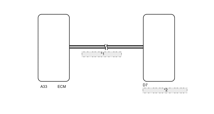
| *1 | CAN Communication Line |
| *2 | Combination Meter Assembly |
PROCEDURE
-
CHECK FOR DTC (METER / GAUGE SYSTEM)
-
Check if meter / gauge system DTCs are output ( Click here).
OK DTCs are not output.
NG 
GO TO DIAGNOSTIC TROUBLE CODE CHART Click here
OK 
-
-
CHECK FOR DTC (SFI SYSTEM)
-
Check if SFI system DTCs are output ( Click here).
OK DTCs are not output.
NG
GO TO SFI SYSTEM Click here
OK
-
-
CHECK TELLTALE LIGHT (WATER TEMPERATURE WARNING (COLD))
-
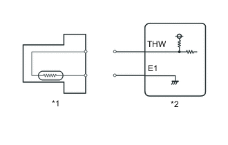
Text In Illustration *1 Engine Coolant Temperature Sensor *2 ECM Disconnect the engine coolant temperature sensor connector.
-
Turn the ignition switch to ON.
-
Check the operating condition of the water temperature warning light.
Result Result Proceed to Water temperature warning light (blue) is on. A Water temperature warning light (blue) is not on. B
B
REPLACE COMBINATION METER ASSEMBLY Click here
A
-
-
CHECK TELLTALE LIGHT (WATER TEMPERATURE WARNING (HOT))
-
Disconnect the engine coolant temperature sensor connector.
-
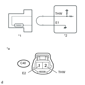
Text In Illustration *1 Engine Coolant Temperature Sensor *2 ECM *3 Front view of wire harness connector
(to Engine Coolant Temperature Sensor)
Connect terminals 1 and 2 of the engine coolant temperature sensor connector on the wire harness side.
-
Turn the ignition switch to ON.
-
Check the operating condition of the water temperature warning light.
Result Result Proceed to Water temperature warning light (red) is on. A Water temperature warning light (red) is not on. B
B
REPLACE COMBINATION METER ASSEMBLY Click here
A
-
-
INSPECT ENGINE COOLANT TEMPERATURE SENSOR
-
Inspect the engine coolant temperature sensor ( Click here).
OK
REPLACE ECM Click here
NG
REPLACE ENGINE COOLANT TEMPERATURE SENSOR Click here
-