METER / GAUGE SYSTEM Tachometer Malfunction
DESCRIPTION
The combination meter assembly controls the tachometer in accordance with the engine speed signals from the ECM through the CAN communication system.
WIRING DIAGRAM
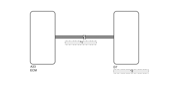
| *1 | CAN Communication Line |
| *2 | COMBINATION METER ASSEMBLY |
PROCEDURE
-
CHECK CAN COMMUNICATION SYSTEM
-
Check if CAN communication DTCs are output Click here.
Result Result Proceed to DTCs are not output A DTCs are output B
B 
GO TO CAN COMMUNICATION SYSTEM Click here
A 
-
-
PERFORM ACTIVE TEST USING GTS (TACHOMETER OPERATION)
-
Connect the GTS to the DLC3.
-
Turn the ignition switch to ON.
-
Turn the GTS on.
-
Enter the following menus: Body Electrical / Combination Meter / Active Test.
-
According to the display on the tester, perform the Active Test.
Combination Meter Tester Display Test Part Control Range Diagnostic Note Tachometer Operation Tachometer 0, 1000, 2000, 3000, , 4000, 5000, 6000, 7000 rpm - OK The engine speed displayed on the tester is approximately the same as that of the tachometer reading.
NG
REPLACE COMBINATION METER ASSEMBLY Click here
OK
-
-
READ VALUE USING GTS (ENGINE RPM)
-
Connect the GTS to the DLC3.
-
Start the engine.
-
Turn the GTS on.
-
Enter the following menus: Body Electrical / Combination Meter / Data List.
-
According to the display on the tester, read the Data List.
Combination Meter Tester Display Measurement Item/Range Normal Condition Diagnostic Note Engine Rpm Engine speed
Min.: 0
Max.: 12750
Approximately same as actual engine speed (when engine is running) Unit: rpm OK The engine speed displayed on the tester is approximately the same as that displayed on the combination meter assembly. Note
Determine whether the value displayed on the tester is within the acceptable range by referring to the reference values described in "On-Vehicle Inspection" Click here.
NG
REPLACE COMBINATION METER ASSEMBLY Click here
OK
-
-
CHECK SFI SYSTEM
-
Check if the SFI system outputs DTCs Click here.
Result Result Proceed to DTCs are not output A DTCs are output B
B
GO TO SFI SYSTEM Click here
A
-
-
READ VALUE USING GTS (ENGINE SPEED)
-
Connect the GTS to the DLC3.
-
Start the engine.
-
Turn the GTS on.
-
Enter the following menus: Powertrain / Engine / Data List.
-
According to the display on the tester, read the Data List.
Combination Meter Tester Display Measurement Item/Range Normal Condition Diagnostic Note Engine Speed Engine speed
Min.: 0
Max.: 16383.75
Approximately same as actual engine speed (when engine is running) Unit: rpm OK The engine speed displayed on the tester is approximately the same as that displayed on the combination meter assembly. Note
Determine whether the value displayed on the tester is within the acceptable range by referring to the reference values described in "On-Vehicle Inspection" Click here.
NG
GO TO SFI SYSTEM Click here
OK
-
-
REPLACE COMBINATION METER ASSEMBLY
-
Replace the combination meter assembly with a new or a normal one Click here.
OK The operation of the tachometer returns to normal.
OK
END
NG
REPLACE ECM Click here
-