METER / GAUGE SYSTEM Tachometer Malfunction
DESCRIPTION
The combination meter assembly controls the tachometer in accordance with the engine speed signals from the ECM through the CAN communication system.
WIRING DIAGRAM
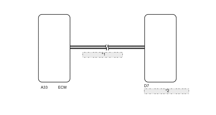
| *1 | CAN Communication Line |
| *2 | Combination Meter Assembly |
PROCEDURE
-
CHECK FOR DTC (METER / GAUGE SYSTEM)
-
Check if meter gauge system DTCs are output Click here.
OK DTCs are not output.
NG 
GO TO DIAGNOSTIC TROUBLE CODE CHART Click here
OK 
-
-
CHECK FOR DTC (SFI SYSTEM)
-
Check if the SFI system outputs DTCs Click here.
OK DTCs are not output.
NG
GO TO SFI SYSTEM Click here
OK
-
-
PERFORM ACTIVE TEST USING GTS (TACHOMETER OPERATION)
-
Connect the GTS to the DLC3.
-
Turn the ignition switch to ON.
-
Turn the GTS on.
-
Enter the following menus: Body Electrical / Combination Meter / Active Test.
-
According to the display on the tester, perform the Active Test.
Combination Meter Tester Display Test Part Control Range Diagnostic Note Tachometer Operation Tachometer 0, 1000, 2000, 3000, , 4000, 5000, 6000, 7000 rpm - OK The engine speed displayed on the tester is approximately the same as that of the tachometer reading.
OK
REPLACE ECM Click here
NG
REPLACE COMBINATION METER ASSEMBLY Click here
-