LIGHTING SYSTEM Door Unlock Detection Switch Circuit
DESCRIPTION
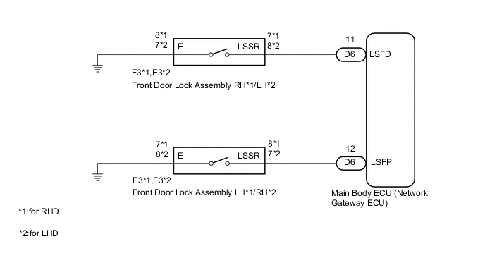
The main body ECU (network gateway ECU) detects the condition of each door unlock detection switch.
WIRING DIAGRAM
PROCEDURE
-
READ VALUE USING GTS
-
Connect the GTS to the DLC3.
-
Turn the ignition switch to ON.
-
Turn the GTS on.
-
Enter the following menus: Body Electrical / Main Body / Data List.
-
Read the display on the GTS.
Main Body Tester Display Measurement Item/Range Normal Condition Diagnostic Note D-Door Lock Pos SW Driver side door unlock detection switch signal/LOCK or UNLOCK LOCK: Driver side door locked
UNLOCK: Driver side door unlocked
- P-Door Lock Pos SW Passenger side door unlock detection switch signal/LOCK or UNLOCK LOCK: Passenger side door locked
UNLOCK: Passenger side door unlocked
- Result Result Proceed to OK A Driver side door unlock detection switch LH does not operate B Passenger side door unlock detection switch RH does not operate C
A 
PROCEED TO NEXT SUSPECTED AREA SHOWN IN PROBLEM SYMPTOMS TABLE Click here
C 
INSPECT FRONT DOOR LOCK ASSEMBLY (for PASSENGER SIDE) Click here
B 
-
-
INSPECT FRONT DOOR LOCK ASSEMBLY (for DRIVER SIDE)
-
Remove the front door lock assembly (for driver side) Click here.
-
Inspect the front door lock assembly (for driver side) Click here.
OK Front door lock assembly (for driver side) is normal.
NG
REPLACE FRONT DOOR LOCK ASSEMBLY (for DRIVER SIDE) Click here
OK
-
-
CHECK HARNESS AND CONNECTOR (FRONT DOOR LOCK ASSEMBLY - MAIN BODY ECU (NETWORK GATEWAY ECU) AND BODY GROUND)
-
Disconnect the E3 front door lock assembly connector.
-
Disconnect the D6 main body ECU (network gateway ECU) connector.
-
Measure the resistance according to the value(s) in the table below.
Standard Resistance for RHD Tester Connection Condition Specified Condition D6-12 (LSFP) - E3-8 (LSSR) Always Below 1 Ω E3-8 (LSSR) - Body ground Always 10 kΩ or higher E3-7 (E) - Body ground Always Below 1 Ω Standard Resistance for LHD Tester Connection Condition Specified Condition D6-11 (LSFD) - E3-8 (LSSR) Always Below 1 Ω E3-8 (LSSR) - Body ground Always 10 kΩ or higher E3-7 (E) - Body ground Always Below 1 Ω
OK
REPLACE MAIN BODY ECU (NETWORK GATEWAY ECU) Click here
NG
REPAIR OR REPLACE HARNESS OR CONNECTOR
-
-
INSPECT FRONT DOOR LOCK ASSEMBLY (for PASSENGER SIDE)
-
Remove the front door lock assembly (for passenger side) Click here.
-
Inspect the front door lock assembly (for passenger side) Click here.
OK Front door lock assembly (for passenger side) is normal.
NG
REPLACE FRONT DOOR LOCK ASSEMBLY (for PASSENGER SIDE) Click here
OK
-
-
CHECK HARNESS AND CONNECTOR (FRONT DOOR LOCK ASSEMBLY - MAIN BODY ECU (NETWORK GATEWAY ECU) AND BODY GROUND)
-
Disconnect the F3 front door lock assembly connector.
-
Disconnect the D6 main body ECU (network gateway ECU) connector.
-
Measure the resistance according to the value(s) in the table below.
Standard Resistance for RHD Tester Connection Condition Specified Condition D6-11 (LSFD) - F3-7 (LSSR) Always Below 1 Ω F3-7 (LSSR) - Body ground Always 10 kΩ or higher F3-8 (E) - Body ground Always Below 1 Ω Standard Resistance for LHD Tester Connection Condition Specified Condition D6-12 (LSFP) - F3-7 (LSSR) Always Below 1 Ω F3-7 (LSSR) - Body ground Always 10 kΩ or higher F3-8 (E) - Body ground Always Below 1 Ω
OK
REPLACE MAIN BODY ECU (NETWORK GATEWAY ECU) Click here
NG
REPAIR OR REPLACE HARNESS OR CONNECTOR
-