LIGHTING SYSTEM Ignition Key Cylinder Light Circuit
DESCRIPTION
The main body ECU (network gateway ECU) controls the operation of the transponder key amplifier (ignition key cylinder light).
WIRING DIAGRAM
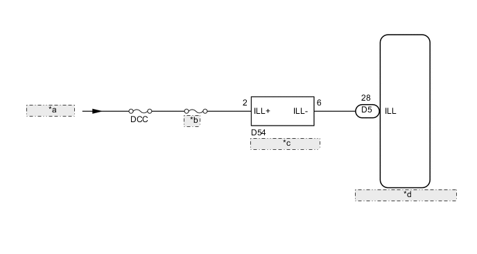
| *a | from Battery |
| *b | DOME |
| *c | Transponder Key Amplifier |
| *d | Main Body ECU (Network Gateway ECU) |
CAUTION / NOTICE / HINT
Note
Inspect the fuses for circuits related to this system before performing the following inspection procedure.
PROCEDURE
-
PERFORM ACTIVE TEST USING GTS
-
Connect the GTS to the DLC3.
-
Turn the ignition switch to ON.
-
Turn the GTS on.
-
Enter the following menus: Body Electrical / Main Body / Active Test.
-
Check that the light operate.
ON Ignition key cylinder light comes on Main Body Tester Display Test Part Control Range Diagnostic Note Key Ring Light Ignition key cylinder light ON/OFF -
OK 
PROCEED TO NEXT SUSPECTED AREA SHOWN IN PROBLEM SYMPTOMS TABLE Click here
NG 
-
-
INSPECT TRANSPONDER KEY AMPLIFIER
-
Remove the transponder key amplifier Click here.
-
Inspect the transponder key amplifier Click here.
OK Transponder key amplifier is normal.
NG
REPLACE TRANSPONDER KEY AMPLIFIER Click here
OK
-
-
CHECK HARNESS AND CONNECTOR (TRANSPONDER KEY AMPLIFIER - BATTERY)
-
Disconnect the D54 transponder key amplifier connector.
-
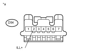
Text in Illustration *a Front view of wire harness connector
(to transponder key amplifier)
Measure the voltage according to the value(s) in the table below.
Standard Voltage Tester Connection Condition Specified Condition D54-2 (ILL+) - Body ground Always 11 to 14 V
NG
REPAIR OR REPLACE HARNESS OR CONNECTOR
OK
-
-
CHECK HARNESS AND CONNECTOR (TRANSPONDER KEY AMPLIFIER - MAIN BODY ECU (NETWORK GATEWAY ECU))
-
Disconnect the D54 transponder key amplifier connector.
-
Disconnect the D5 main body ECU (network gateway ECU) connector.
-
Measure the resistance according to the value(s) in the table below.
Standard Resistance Tester Connection Condition Specified Condition D54-6 (ILL-) - D5-28 (ILL) Always Below 1 Ω D5-28 (ILL) - Body ground Always 10 kΩ or higher
OK
REPLACE MAIN BODY ECU (NETWORK GATEWAY ECU) Click here
NG
REPAIR OR REPLACE HARNESS OR CONNECTOR
-