THEFT DETERRENT SYSTEM TERMINALS OF ECU
-
CHECK INSTRUMENT PANEL JUNCTION BLOCK ASSEMBLY AND MAIN BODY ECU (NETWORK GATEWAY ECU)
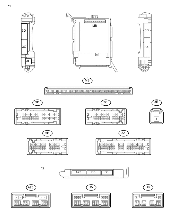
Text in Illustration *1 Instrument Panel Junction Block Assembly *2 Main Body ECU (Network Gateway ECU)
-
Remove the main body ECU (network gateway ECU) from the instrument panel junction block assembly Click here.
-
Measure the voltage and resistance according to the value(s) in the table below.
Terminal No. (Symbol) Wiring Color Terminal Description Condition Specified Condition MB-1 (BECU) - Body ground None - Body ground Battery power supply Always 11 to 14 V MB-8 (IG) - Body ground None - Body ground Engine switch power supply Engine switch on (IG) 11 to 14 V Engine switch off Below 1 V MB-9 (ACC) - Body ground None - Body ground ACC power supply Engine switch on (ACC) 11 to 14 V Engine switch off Below 1 V MB-11 (GND) - Body ground None - Body ground Ground Always Below 1 Ω MB-32 (BMPX) - Body ground None - Body ground Battery power supply Always 11 to 14 V D6-1 (GND) - Body ground B - Body ground Ground Always Below 1 Ω A73-4 (GND) - Body ground B-Y - Body ground Ground Always Below 1 Ω If the result is not as specified, there may be a malfunction in the wire harness.
-
Install the main body ECU (network gateway ECU) to the instrument panel junction block assembly Click here.
-
Measure the voltage and waveform according to the value(s) in the table below.
Terminal No. (Symbol) Wiring Color Terminal Description Condition Specified Condition 3A-28 - Body ground V - Body ground Driver side door courtesy light switch input Driver side door open Below 1 V Driver side door closed 11 to 14 V 3B-13 - Body ground GR - Body ground Passenger side door courtesy light switch input Passenger side door open Below 1 V Passenger side door closed 11 to 14 V 3B-22 - Body ground V - Body ground Security indicator light signal Security indicator light illuminated (illuminates only for 60 seconds in alarm sounding state (blinks when system in armed state)) Below 4 V 3D-26 - Body ground SB - Body ground Luggage compartment door courtesy light switch input Luggage compartment door open Below 1 V Engine switch off, all doors closed and luggage compartment door closed 11 to 14 V 3D-31 - Body ground BR - Body ground Vehicle horn signal Vehicle horns sounding (Theft deterrent system is in alarm sounding state) Pulse generation Vehicle horns not sounding (Theft deterrent system is in armed state) 11 to 14 V 3B-2 - Body ground V - Body ground Door lock motor lock drive output (for driver side) Driver side door control switch not pushed Below 1 V Lock side of driver side door control switch pushed 11 to 14 V 3B-3 - Body ground L - Body ground Door lock motor lock drive output (for passenger side) Driver side door control switch not pushed Below 1 V Lock side of driver side door control switch pushed 11 to 14 V 3B-1 - Body ground R-G - Body ground Door lock motor unlock drive output (for driver side) Driver side door control switch not pushed Below 1 V Unlock side of driver side door control switch pushed 11 to 14 V 3B-4 - Body ground L-W - Body ground Door lock motor unlock drive output (for passenger side) Driver side door control switch not pushed Below 1 V Unlock side of driver side door control switch pushed 11 to 14 V D5-22 (ACC) - Body ground W - Body ground ACC power supply Engine switch on (ACC) 11 to 14 V Engine switch off Below 1 V D6-11 (LSFD) - Body ground W - Body ground Driver side door unlock detection switch input Driver side door unlocked Below 1 V Engine switch off, all doors closed and driver side door locked Pulse generation (See waveform 1 or 2) D6-12 (LSFP) - Body ground SB - Body ground Passenger side door unlock detection switch input Passenger side door unlocked Below 1 V Engine switch off, all doors closed and passenger side door locked Pulse generation (See waveform 1 or 2) -
Inspect using an oscilloscope.
Note
The oscilloscope waveform shown in the illustration is an example for reference only. Noise, chattering, etc. are not shown.
-
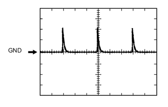
Waveform 1 (Reference)
Measurement Condition Item Content Tester Connection D6-11 (LSFD) - Body ground Tool Setting 5 V/DIV., 20 ms/DIV. Condition Engine switch off, all doors closed and driver side door locked Measurement Condition Item Content Tester Connection D6-12 (LSFP) - Body ground Tool Setting 5 V/DIV., 20 ms/DIV. Condition Engine switch off, all doors closed and passenger side door locked -
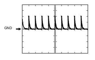
Waveform 2 (Reference)
Measurement Condition Item Content Tester Connection D6-11 (LSFD) - Body ground Tool Setting 5 V/DIV., 20 ms/DIV. Condition Engine switch off, all doors closed and driver side door locked Measurement Condition Item Content Tester Connection D6-12 (LSFP) - Body ground Tool Setting 5 V/DIV., 20 ms/DIV. Condition Engine switch off, all doors closed and passenger side door locked
-
-