ENGINE IMMOBILISER SYSTEM(w/o Entry and Start System) Security Indicator Light Does not Blink
DESCRIPTION
-
When the engine immobiliser system is set, the security indicator light blinks continuously, but does not illuminate if the engine immobiliser system is not set.
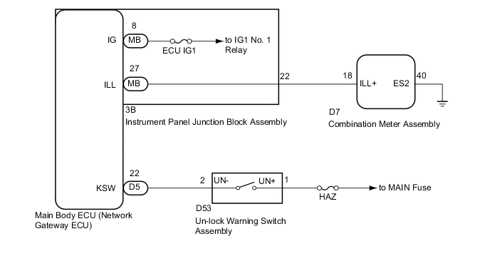
WIRING DIAGRAM
CAUTION / NOTICE / HINT
Note
-
Inspect the fuses for circuits related to this system before performing the following inspection procedure.
-
If the combination meter assembly and main body ECU (network gateway ECU) is replaced, refer to Service Bulletin.
PROCEDURE
-
CHECK FOR DTC
-
Check for DTCs Click here.
OK DTC is not output.
NG 
GO TO DTC CHART Click here
OK 
-
-
PERFORM ACTIVE TEST USING GTS (SECURITY INDICATOR)
-
Check that the security indicator light illuminates when operating it with the Active Test Click here.
Main Body Tester Display Test Part Control Range Diagnostic Note Security Indicator Security indicator light ON/OFF - OK Security indicator light can be turned on and off using the GTS.
NG 
CHECK HARNESS AND CONNECTOR (INSTRUMENT PANEL JUNCTION BLOCK - COMBINATION METER ASSEMBLY) Click here
OK
-
-
READ VALUE USING GTS (IG SW, KEY UNLOCK WARNING SW)
-
Connect the GTS to the DLC3.
-
Turn the ignition switch to ON.
-
Turn the GTS on.
-
Enter the following menus: Body Electrical / Main Body / Data List.
-
Read the Data List according to the display on the GTS.
Main Body Tester Display Measurement Item/Range Normal Condition Diagnostic Note IG SW Ignition switch ON signal / OFF or ON OFF: Ignition switch ACC or off
ON: Ignition switch ON
- Key Unlock Warning SW Un-lock warning switch signal / OFF or ON OFF: No key in ignition key cylinder
ON: Key inserted in ignition key cylinder
- OK On the GTS screen, the display changes between ON and OFF according to the chart above. Result Result Proceed to OK A NG (IG SW) B NG (Key Unlock Warning SW) C
A
REPLACE MAIN BODY ECU (NETWORK GATEWAY ECU) Click here
B
GO TO LIGHTING SYSTEM (IG Signal Circuit) Click here
C
-
-
INSPECT UN-LOCK WARNING SWITCH ASSEMBLY
-
Remove the un-lock warning switch assembly Click here.
-
Inspect the un-lock warning switch assembly Click here.
NG
REPLACE UN-LOCK WARNING SWITCH ASSEMBLY Click here
OK
-
-
CHECK HARNESS AND CONNECTOR (UN-LOCK WARNING SWITCH ASSEMBLY - MAIN BODY ECU)
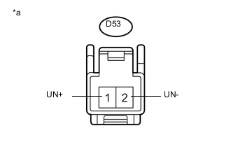
Text in Illustration *a Front view of wire harness connector
(to Un-lock Warning Switch Assembly)
-
Disconnect the D5 main body ECU (network gateway ECU) connector.
-
Measure the voltage and resistance according to the value(s) in the table below.
Standard Voltage Tester Connection Condition Specified Condition D53-1 (UN+) - Body ground Always 11 to 14 V Standard Resistance Tester Connection Condition Specified Condition D53-2 (UN-) - D5-22 (KSW) Always Below 1 Ω D53-2 (UN-) - Body ground Always 10 kΩ or higher
OK
REPLACE MAIN BODY ECU (NETWORK GATEWAY ECU) Click here
NG
REPAIR OR REPLACE HARNESS OR CONNECTOR
-
-
CHECK HARNESS AND CONNECTOR (INSTRUMENT PANEL JUNCTION BLOCK - COMBINATION METER ASSEMBLY)
-
Disconnect the 3B instrument panel junction block assembly connector.
-
Disconnect the D7 combination meter assembly connector.
-
Measure the resistance according to the value(s) in the table below.
Standard Resistance Tester Connection Condition Specified Condition 3B-22 - D7-18 Always Below 1 Ω D7-40 - Body ground Always Below 1 Ω 3B-22 - Body ground Always 10 kΩ or higher
NG
REPAIR OR REPLACE HARNESS OR CONNECTOR
OK
-
-
INSPECT INSTRUMENT PANEL JUNCTION BLOCK ASSEMBLY
-
Remove the instrument panel junction block assembly Click here.
-
Remove the main body ECU (network gateway ECU) from the instrument panel junction block assembly.
-
Measure the resistance according to the value(s) in the table below.
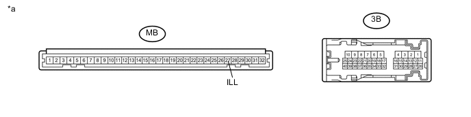
Text in Illustration *a Component without harness connected
(Instrument Panel Junction Block Assembly )
- - Standard Resistance Tester Connection Condition Specified Condition MB-27 (ILL) - 3B-22 Always Below 1 Ω
NG
REPLACE INSTRUMENT PANEL JUNCTION BLOCK ASSEMBLY Click here
OK
-
-
REPLACE COMBINATION METER ASSEMBLY
-
Replace the combination meter assembly with a new one Click here.
-
When the immobiliser is set, check that the security indicator light blinks.
OK Security indicator light blinks.
OK
END (COMBINATION METER ASSEMBLY WAS DEFECTIVE)
NG
REPLACE MAIN BODY ECU (NETWORK GATEWAY ECU) Click here
-