ENGINE IMMOBILISER SYSTEM(w/ Entry and Start System), Diagnostic DTC:B1572
| DTC Code | DTC Name |
|---|---|
| B1572 | Immobiliser System Communication Malfunction |
DESCRIPTION
The ECM stores this code if a communication problem is detected between the ID code box (immobiliser code ECU)*1 or certification ECU (smart key ECU assembly)*2 and the ECM.
-
*1: w/ ID Code Box
-
*2: w/o ID Code Box
| DTC Code | DTC Detection Condition | Trouble Area | DTC Output Confirmation Operation |
|---|---|---|---|
| B1572 | When there is a problem in communication between the ID code box (immobiliser code ECU)*1 or certification ECU (smart key ECU assembly)*2 and the ECM (1 trip detection logic*3): |
|
Engine switch on (IG) |
-
*1: w/ ID Code Box
-
*2: w/o ID Code Box
-
*3: Only output while a malfunction is present.
| Vehicle Condition when Malfunction Detected | Fail-safe Operation when Malfunction Detected |
|---|---|
| Engine cannot be started | - |
| DTC Code | Data List and Active Test |
|---|---|
| B1572 |
Entry&Start |
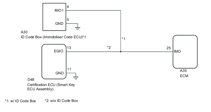
WIRING DIAGRAM
CAUTION / NOTICE / HINT
Note
-
Before replacing the certification ECU or ID code box (immobiliser code ECU)*, refer to the entry and start system (for Entry Function) Click here.
-
After performing repairs, perform the operation that fulfills the DTC output confirmation operation, and then confirm that no DTCs are output again.
-
*: w/ ID Code Box
PROCEDURE
-
READ VALUE USING GTS (IMMOBILISER)
-
Connect the GTS to the DLC3.
-
Turn the engine switch on (IG).
-
Turn the GTS on.
-
Enter the following menus: Body Electrical / Entry & Start / Data List.
-
According to the display on the GTS, read the Data List.
Entry & Start Tester Display Measurement Item/Range Normal Condition Diagnostic Note Immobiliser Engine immobiliser system status when power source mode on (IG) / Unset or Set Set: Engine immobiliser set (engine start prohibited) (engine switch off)
Unset: Engine immobiliser unset (engine start permitted) [engine switch on (ACC) or on (IG)]
If "Set" is displayed, the engine start function is prohibited. OK On the GTS screen, the display changes between Set and Unset as shown in the table above.
NG 
GO TO ENTRY AND START SYSTEM (ENGINE DOES NOT START) Click here
OK 
-
-
CHECK VEHICLE CONDITION
-
Check the vehicle condition.
Result Proceed to w/ ID Code Box A w/o ID Code Box B
B 
CHECK HARNESS AND CONNECTOR Click here
A
-
-
CHECK HARNESS AND CONNECTOR
-
Disconnect the A30 ID code box (immobiliser code ECU) connector.
-
Disconnect the A35 ECM connector.
-
Measure the resistance according to the value(s) in the table below.
Standard Resistance Tester Connection Condition Specified Condition A30-4 (IMO1) - A35-25 (IMO) Always Below 1 Ω A30-4 (IMO1) - Body ground Always 10 kΩ or higher
NG
REPAIR OR REPLACE HARNESS OR CONNECTOR
OK
-
-
REPLACE ECM
-
Temporarily replace the ECM with a new one Click here.
NEXT
-
-
REGISTER ECU COMMUNICATION ID
-
Register the ECU communication ID (Refer to Service Bulletin).
-
Check that the engine can be started.
OK The engine can be started.
OK
END (ECM WAS DEFECTIVE)
NG
ID CODE BOX (IMMOBILIZER CODE ECU)
-
-
CHECK HARNESS AND CONNECTOR
-
Disconnect the D48 certification ECU (smart key ECU assembly) connector.
-
Disconnect the A35 ECM connector.
-
Measure the resistance according to the value(s) in the table below.
Standard Resistance Tester Connection Condition Specified Condition D48-13 (EGIO) - A35-25 (IMO1) Always Below 1 Ω D48-13 (EGIO) - Body ground Always 10 kΩ or higher
NG
REPAIR OR REPLACE HARNESS OR CONNECTOR
OK
-
-
REPLACE ECM
-
Temporarily replace the ECM with a new one Click here.
NEXT
-
-
REGISTER ECU COMMUNICATION ID
-
Register the ECU communication ID (Refer to Service Bulletin).
-
Check that the engine can be started.
OK The engine can be started.
OK
END (ECM WAS DEFECTIVE)
NG
REPLACE CERTIFICATION ECU (SMART KEY ECU ASSEMBLY)
-