ENGINE IMMOBILISER SYSTEM(w/o Entry and Start System), Diagnostic DTC:B1409
| DTC Code | DTC Name |
|---|---|
| B1409 | SCU Communication Circuit |
DESCRIPTION
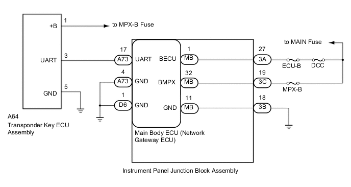
The main body ECU (network gateway ECU) stores this code if a communication problem is detected between the main body ECU (network gateway ECU) and the transponder key ECU assembly.
| DTC Code | DTC Detection Condition | Trouble Area |
|---|---|---|
| B1409 | When there is a problem in communication between the main body ECU (network gateway ECU) and the transponder key ECU assembly. |
|
WIRING DIAGRAM
CAUTION / NOTICE / HINT
Note
-
If the main body ECU (network gateway ECU) or transponder key ECU assembly is replaced, refer to Service Bulletin.
-
Inspect the fuses for circuits related to this system before performing the following inspection procedure.
PROCEDURE
-
CHECK HARNESS AND CONNECTOR (INSTRUMENT PANEL JUNCTION BLOCK - BATTERY, BODY GROUND)
-
Disconnect the A73 and D6 main body ECU (network gateway ECU) connectors.
-
Disconnect the 3A, 3B and 3C instrument panel junction block assembly connectors.
-
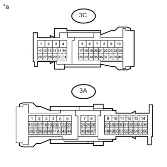
Text in Illustration *a Component without harness connected
(Instrument Panel Junction Block Assembly)
Measure the voltage according to the value(s) in the table below.
Standard Voltage Tester Connection Condition Specified Condition 3A-27 - Body ground Always 11 to 14 V 3C-19 - Body ground Always 11 to 14 V -
Measure the resistance according to the value(s) in the table below.
Standard Resistance Tester Connection Condition Specified Condition 3B-18 - Body ground Always Below 1 Ω A73-4 (GND) - Body ground Always Below 1 Ω D6-1 (GND) - Body ground Always Below 1 Ω
NG 
REPAIR OR REPLACE HARNESS OR CONNECTOR
OK 
-
-
INSPECT INSTRUMENT PANEL JUNCTION BLOCK ASSEMBLY
-
Remove the instrument panel junction block assembly Click here.
-
Remove the main body ECU (network gateway ECU) from the instrument panel junction block assembly.
-
Measure the resistance according to the value(s) in the table below.
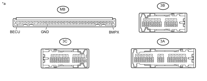
Text in Illustration *a Component without harness connected
(Instrument Panel Junction Block Assembly)
- - Standard Resistance Tester Connection Condition Specified Condition MB-1 (BECU) - 3A-27 Always Below 1 Ω MB-32 (BMPX) - 3C-19 Always Below 1 Ω MB-11 (GND) - 3B-18 Always Below 1 Ω
NG
REPLACE INSTRUMENT PANEL JUNCTION BLOCK ASSEMBLY Click here
OK
-
-
CHECK HARNESS AND CONNECTOR (TRANSPONDER KEY ECU ASSEMBLY - BATTERY, BODY GROUND)
-
Disconnect the A64 transponder key ECU assembly connector.
-
Measure the voltage according to the value(s) in the table below.
Standard Voltage Tester Connection Condition Specified Condition A64-1 (+B) - Body ground Always 11 to 14 V -
Measure the resistance according to the value(s) in the table below.
Standard Resistance Tester Connection Condition Specified Condition A64-5 (GND) - Body ground Always Below 1 Ω
NG
REPAIR OR REPLACE HARNESS OR CONNECTOR
OK
-
-
CHECK HARNESS AND CONNECTOR (MAIN BODY ECU - TRANSPONDER KEY ECU ASSEMBLY)
-
Measure the voltage and resistance according to the value(s) in the table below.
Standard Voltage Tester Connection Condition Specified Condition A73-17 (UART) - Body ground Always Below 1 V Standard Resistance Tester Connection Condition Specified Condition A73-17 (UART) - A64-3 (UART) Always Below 1 Ω A73-17 (UART) - Body ground Always 10 kΩ or higher
NG
REPAIR OR REPLACE HARNESS OR CONNECTOR
OK
-
-
REPLACE TRANSPONDER KEY ECU ASSEMBLY
-
Replace the transponder key ECU assembly with a new one (Refer to Service Bulletin).
NEXT
-
-
CHECK FOR DTC
-
Check for DTCs Click here.
OK DTC B1409 is not output
OK
END (TRANSPONDER KEY ECU ASSEMBLY WAS DEFECTIVE)
NG
REPLACE MAIN BODY ECU (NETWORK GATEWAY ECU) Click here
-