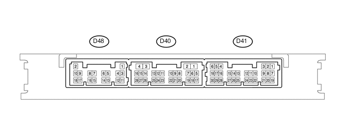
ENTRY AND START SYSTEM(for Start Function) TERMINALS OF ECU
Tech Tips
-
For the layout of the certification ECU (smart key ECU assembly) (verification-related) terminals, refer to the following Click here.
-
For the layout of the ID code box (immobiliser code ECU) terminals, refer to the following Click here.
-
For the layout of the steering lock actuator assembly (steering lock ECU) terminals, refer to the following Click here.
-
CHECK CERTIFICATION ECU (SMART KEY ECU ASSEMBLY)
-
Disconnect the D41 and D48 certification ECU (smart key ECU assembly) connectors.
-
Measure the voltage and resistance according to the value(s) in the table below.
Terminal No. (Symbol) Input/Output Wiring Color Terminal Description Condition Specified Condition Related Data List Item D41-4 (ACCD) - Body ground Output SB - Body ground ACC signal 20°C (68°F) 81.49 to 118.98 Ω ACC Relay Monitor D41-6 (IG1D) - Body ground Output W - Body ground IG1 signal 20°C (68°F) 40.74 to 54.49 Ω IG1 Relay Monitor (Outside) D41-25 (P) - D48- 11 (GND)*1 Input Y - B Shift lever P position switch signal Shift lever in P → Shift lever not in P Below 200 Ω → 40 kΩ or higher Shift P Signal D41-26 (SLP) - D48- 11 (GND) Input LG - B Steering lock bar position signal Always 10 kΩ or higher Steering Unlock Switch D41-27 (SPD) - Body ground Input P - Body ground Vehicle speed signal Always 30 kΩ or higher Vehicle Speed D41-28 (SSW1) - Body ground Input P - Body ground SSW1 contact signal Engine switch pushed → Engine switch not pushed Below 1 Ω → 10 kΩ or higher Start Switch1 D41-30 (SSW2) - Body ground Input BE - Body ground SSW2 contact signal (backup for SSW1 and has same behavior as SSW1)
Tech Tips
Backup for SSW1. Behaves the same way as SSW1.
Engine switch pushed → Engine switch not pushed Below 1 Ω → 10 kΩ or higher Start Switch2 D48-11 (GND) - Body ground - B - Body ground Ground Always Below 1 Ω - D48-9 (IG2D) - Body ground Output V - Body ground IG2 signal 20°C (68°F) 74.15 to 460.88 Ω IG2 Relay Monitor (Outside) D48-2 (+B) - Body ground Input R - Body ground +B power supply Always 11 to 14 V - D48-17 (TACH) - Body ground Input GR - Body ground Engine speed signal Always 10 kΩ or higher Engine Condition D48-18 (STP1) - Body ground*1 Input L - Body ground Stop light switch signal Brake pedal depressed → Brake pedal released 9 V or higher → 1 V or less Stop Light Switch1
-
*1: for Automatic Transmission
-
*2: for Manual Transaxle
If the result is not as specified, there may be a malfunction in the wire harness.
-
-
Reconnect the D41 and D48 certification ECU (smart key ECU assembly) connectors.
-
Measure the voltage and check for pulses according to the value(s) in the table below.
Terminal No. (Symbol) Input/Output Wiring Color Terminal Description Condition Specified Condition Related Data List Item D41-25 (P) - D48-11 (GND)*1 Input Y - B Shift lever P position switch signal Shift lever in P →Shift lever not in P 1.5 V or less → 9 V or higher Shift P Signal D41-4 (ACCD) - D48-11 (GND) Output SB - B ACC signal Engine switch off → Engine switch on (ACC) 1 V or less → 8.5 V or higher ACC Relay Monitor D41-6 (IG1D) - D48-11 (GND) Output W - B IG1 signal Engine switch on (ACC) → Engine switch on (IG) 1 V or less → 9 V or higher IG1 Relay Monitor(Outside) D41-26 (SLP) - D48-11 (GND) Input LG - B Steering lock bar position signal Steering locked → Steering unlocked*3 11 to 14 V → 1.2 V or less Steering Unlock Switch D41-27 (SPD) - D48-11 (GND) Input P - B Vehicle speed signal Engine switch on (IG), vehicle being driven at approx. 5 km/h (3 mph) Pulse generation
(See waveform 1)
Vehicle Speed D41-28 (SSW1) - D48-11 (GND) Input P - B Engine switch signal Engine switch not pushed → Engine switch pushed 9 V or higher → 1 V or less Start Switch1 D41-29 (SLR+) - D48-11 (GND) Output Y - B Steering lock motor activation command signal (motor activation permission signal sent from certification ECU (smart key ECU assembly)) Steering lock motor operating → Steering lock motor not operating → Steering lock motor operating*4 Pulse generation
(See waveform 2)
- D41-30 (SSW2) - D48-11 (GND) Input BE - B SSW2 contact signal
Tech Tips
Backup for SSW1. Behaves the same way as SSW1.
Engine switch not pushed → Engine switch pushed 9 V or higher → 1 V or less Start Switch2 D48-7 (STSW) - D48-11 (GND) Output P - B Starter request signal With the brake pedal*1 or clutch pedal*2 depressed, the engine switch is pressed and held (starter on) → After approx. 1 sec. has elapsed, the engine switch is released (starter off) 2 V or less → 9 V or higher Starter Request Signal D48-5 (N-SW) - Body ground*1 Input W - Body ground Neutral switch signal Engine switch on (IG), shift lever in P or N → Engine switch on (IG), shift lever not in P or N 9 V or higher → 1 V or less Neutral SW/ Clutch SW D48-10 (CLUT) - Body ground*2 Input Y - Body ground Clutch switch signal Perform the following operations except while the engine is cranking:
Clutch pedal released → Clutch pedal depressed
1 V or less → 9 V or higher Neutral SW/ Clutch SW D40-28 (ACCR) - D48-11 (GND) Input BE - B ACC relay cut signal With the brake pedal*1 or clutch pedal*2 depressed, the engine switch is pressed and held (starter on) → After approx. 1 sec. has elapsed, the engine switch is released (starter off) 2 V or less → 9 V or higher ACC Relay Cut Signal D48-17 (TACH) - D48-11 (GND) Input GR - B Crankshaft position sensor signal Idling with warm engine Pulse generation
(See waveform 3)
Engine Condition D48-9 (IG2D) - D48-11 (GND) Output V - B IG2 signal Engine switch on (ACC) → Engine switch on (IG) 1 V or less → 9 V or higher IG2 Relay Monitor(Outside) D48-18 (STP1) - D48-11 (GND)*1 Input L - B Stop light switch signal Brake pedal released → Brake pedal depressed 1 V or less → 9 V or higher Stop Light Switch1
-
*1: for Automatic Transmission
-
*2: for Manual Transaxle
Tech Tips
-
*3: When the shift lever is in P (for Automatic Transmission) and the engine switch is off, if any door is opened or closed, the steering is locked. When the key is inside the vehicle and the engine switch is turned on (ACC) or on (IG), the steering unlocks.
-
*4: The steering lock motor operates when the following conditions are met and a door is opened:
-
The shift lever is in P (for Automatic Transmission).
-
While carrying the electrical key transmitter sub-assembly, the engine switch is turned on (IG) to unlock the steering, and then the engine switch is turned off.
-
-
Using an oscilloscope, check the waveform of the ECU.
Note
The oscilloscope waveform shown in the illustration is an example for reference only. Noise, chattering, etc. are not shown.
-
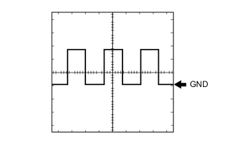
Waveform 1 (Reference)
Item Content Tester Connection D41-27 (SPD) - D48-11 (GND) Tool Setting 5 V/DIV., 100 ms./DIV. Condition Engine switch on (IG), vehicle being driven at approx. 5 km/h (3 mph) Tech Tips
The wavelength becomes shorter as the vehicle speed increases.
-
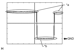
Text in Illustration *a Steering lock motor not operating *b Steering lock motor operating Waveform 2 (Reference)
Item Content Tester Connection D41-29 (SLR+) - D48-11 (GND) Tool Setting 2 V/DIV., 200 ms./DIV. Condition Steering lock motor not operating → Steering lock motor operating → Steering lock motor not operating*1 Tech Tips
*1: When all of the following conditions are met, open any of the doors to operate the steering lock motor.
-
The shift lever is in P*.
-
*: for Automatic Transmission
-
While carrying the electrical key transmitter sub-assembly, the engine switch is turned on (IG) and the steering wheel is unlocked.
-
The engine switch is off.
-
-
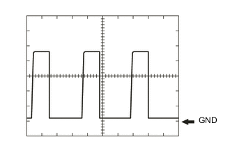
Waveform 3 (Reference)
Item Content Tester Connection D48-17 (TACH) - D48-11 (GND) Tool Setting 2 V/DIV., 2 ms./DIV. Condition Idling with warm engine Tech Tips
The wavelength becomes shorter as the engine speed increases.
-
-
-
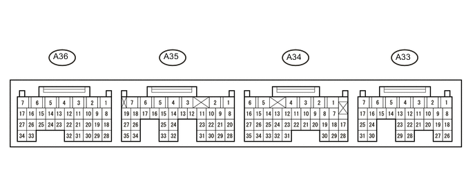
CHECK ECM
-
Measure the resistance and voltage and check for pulses according to the value(s) in the table below.
Terminal No. (Symbol) Input/Output Wiring Color Terminal Description Condition Specified Condition Related Data List Item/DTC A36-4 (E01) - Body ground - B-L - Body ground Ground Always Below 1 Ω - A33-14 (STSW2) - A36-4 (E01) Input BR - B-L Starter switch signal Engine switch on (IG) 1 V or less Starter Control Cranking 6 to 13 V A33-16 (NSW) - A36-4 (E01) Input W-R - B-L*1
G-B - B-L*2
Neutral switch signal Engine switch on (IG), shift lever in not P or N 10 to 13 V - Engine switch on (IG), shift lever in P or N 1 V or less A33-17 (STSW) - A36-4 (E01) Input G-W - B-L Starter request signal Engine switch on (IG) 1 V or less - Cranking 6 V or higher A35-15 (TACH) - A36-4 (E01) Output GR-R - B-L Engine speed signal Idling with warm engine Pulse generation
(See waveform 1)
Engine Speed A35-26 (STA) - A36-4 (E01) Output B-L - B-L*3
B-W - B-L*4
Starter relay signal Engine switch on (IG) 11 to 14 V → 1 V or less Starter Signal Cranking 10 to 13 V A35-32 (ACCR) - A36-4 (E01) Output G-Y - B-L ACC relay cut signal Engine switch on (IG) 10 to 13 V - Cranking 1 V or less A35-34 (STAR) - A36-4 (E01) Output LG-R - B-L Starter relay cut signal Engine switch on (IG) 10 to 13 V Starter Cut Relay Cranking 1 V or less
-
*1: for Automatic Transmission
-
*2: for Manual Transmission
-
*3: w/ Double Locking Function
-
*4: w/o Double Locking Function
If the result is not as specified, the ECM may have a malfunction.
-
-
Inspect using an oscilloscope.
Note
The waveform shown in the illustration is an example for reference only. Noise, chattering, etc. are not shown.
-
Waveform 3 (Reference)
Item Content Tester Connection A35-15 (TACH) - A36-4 (E01) Tool Setting 2 V/DIV., 2 ms./DIV. Condition Idling with warm engine Tech Tips
The wavelength becomes shorter as the engine speed increases.
-
-