WIRELESS DOOR LOCK CONTROL SYSTEM(w/ Entry and Start System) TERMINALS OF ECU
-
CHECK INSTRUMENT PANEL JUNCTION BLOCK ASSEMBLY AND MAIN BODY ECU (NETWORK GATEWAY ECU)

Text in Illustration *1 Instrument Panel Junction Block Assembly *2 Main Body ECU (Network Gateway ECU)
-
Remove the main body ECU (network gateway ECU) from the instrument panel junction block assembly.
-
Disconnect the D6 and A73 main body ECU (network gateway ECU) connectors.
-
Measure the resistance and voltage according to the value(s) in the table below.
Terminal No. (Symbol) Wiring Color Terminal Description Condition Specified Condition MB-11 (GND) - Body ground None - Body ground Ground Always Below 1 Ω MB-1 (BECU) - Body ground None - Body ground Battery power supply Always 11 to 14 V MB-32 (BMPX) - Body ground None - Body ground Battery power supply Always 11 to 14 V MB-8 (IG) - Body ground None - Body ground Engine switch power supply Engine switch on (IG) 11 to 14 V Engine switch off Below 1 V MB-9 (ACC) - Body ground None - Body ground ACC power supply Engine switch on (ACC) 11 to 14 V Engine switch off Below 1 V D6-1 (GND) - Body ground B - Body ground Ground Always Below 1 Ω A73-4 (GND) - Body ground B-Y - Body ground Ground Always Below 1 Ω -
Reconnect the D6 and A73 main body ECU (network gateway ECU) connectors.
-
Install the main body ECU (network gateway ECU) to the instrument panel junction block assembly.
-
Measure the voltage, check for pulse according to the valve(s) in the table below.
Terminal No. (Symbol) Wiring Color Terminal Description Condition Specified Condition 3A-28 - Body ground V - Body ground Driver side door courtesy light switch input Driver side door open Below 1 V Driver side door closed 11 to 14 V 3B-13 - Body ground GR - Body ground Passenger side door courtesy light switch input Passenger side door open Below 1 V Passenger side door closed 11 to 14 V 3D-26 - Body ground SB - Body ground Luggage compartment door courtesy light switch input Luggage compartment door open Below 1 V Luggage compartment door closed 11 to 14 V 3B-2 - Body ground Y - Body ground Door lock motor lock drive output Door control switch not pushed Below 1 V Lock side of door control switch pushed 11 to 14 V 3B-3 - Body ground L - Body ground Door lock motor lock drive output Door control switch not pushed Below 1 V Lock side of door control switch pushed 11 to 14 V 3B-6 - Body ground G - Body ground Door lock motor lock drive output (for luggage compartment door) Luggage open switch of electrical key transmitter sub-assembly not pressed Below 1 V Luggage open switch of electrical key transmitter sub-assembly pressed 11 to 14 V 3B-1 - Body ground*1, *2 R-G - Body ground Door lock motor unlock drive output Door control switch not pushed Below 1 V Unlock side of door control switch pushed 11 to 14 V 3B-4 - Body ground L-W - Body ground Door lock motor unlock drive output Door control switch not pushed Below 1 V Unlock side of door control switch pushed 11 to 14 V A73-1 (BZR) - Body ground V - Body ground Wireless door lock buzzer signal Wireless door lock buzzer off Below 1 V Wireless door lock buzzer on Pulse generation D5-22 (ACC) - Body ground W - Body ground ACC power supply Engine switch off Below 1 V Engine switch on (ACC) 11 to 14 V D6-11 (LSFD) - Body ground W - Body ground Driver side door unlock detection switch input Driver side door unlocked Below 1 V Engine switch off, all doors closed and driver side door locked Pulse generation D6-12 (LSFP) - Body ground SB - Body ground Passenger side door unlock detection switch input Passenger side door unlocked Below 1 V Engine switch off, all doors closed and passenger side door locked Pulse generation
-
*1: w/o Passenger Side Door Control Switch
-
*2: w/o Double Locking System
-
-
-
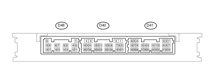
CHECK CERTIFICATION ECU (SMART KEY ECU ASSEMBLY)
-
Disconnect the D48 certification ECU (smart key ECU assembly) connector.
-
Measure the voltage and resistance according to the value(s) in the table below.
Tech Tips
Measure the values on the wire harness side with the connectors disconnected.
Terminal No. (Symbol) Wiring Color Terminal Description Condition Specified Condition D48-2 (+B) - D48-11 (GND) R - B +B power supply Always 11 to 14 V D48-11 (GND) - Body ground B - Body ground Ground Always Below 1 Ω If the result is not as specified, there may be a malfunction in the wire harness.
-
Reconnect the D48 certification ECU (smart key ECU assembly) connector.
-
Measure the voltage according to the value(s) in the table below.
Terminal No. (Symbol) Wiring Color Terminal Description Condition Specified Condition D41-5 (IG2) - D48-11 (GND) Y - B IG power supply Engine switch off → on (IG) Below 1 V → 11 to 14 V D40-5 (RCO) - D48-11 (GND) LG - B Entry door control receiver power source Engine switch off, all doors closed and electrical key transmitter sub-assembly switch not pressed → electrical key transmitter sub-assembly switch pressed Below 1 V → 4.5 to 5.5 V D40-17 (RDA) - D48-11 (GND) P - B Entry door control receiver data input signal Engine switch off, all doors closed and electrical key transmitter sub-assembly switch not pressed → electrical key transmitter sub-assembly switch pressed 11 to 14 V pulse generation at regular intervals D40-19 (RSSI) - D48-11 (GND) R - B Entry door control receiver electric wave existence signal All door locked, all doors closed and electrical key switch on 11 to 14 V → Below 2 V
-
-
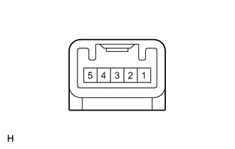
CHECK DOOR CONTROL RECEIVER
-
Disconnect the H26 door control receiver connector.
-
Measure the resistance according to the value(s) in the table below.
Terminal No. (Symbol) Wiring Color Terminal Description Condition Specified Condition H26-1 (GND) - Body ground B - Body ground Ground Always Below 1 Ω -
Reconnect the H26 door control receiver connector.
-
Measure the voltage according to the value(s) in the table below.
Terminal No. (Symbol) Wiring Color Terminal Description Condition Specified Condition H26-2 (RSSI) - H26-1 (GND) BR - B Entry door control receiver electric wave existence signal All door locked, all doors closed and electrical key switch on 11 to 14 V → Below 2 V H26-5 (DATA) - H26-1 (GND) G - B Entry door control receiver data input signal Engine switch off, all doors closed and electrical key transmitter sub-assembly switch not pressed → electrical key transmitter sub-assembly switch pressed 11 to 14 V pulse generation at regular intervals H26-4 (+5) - H26-1 (GND) Y - B Entry door control receiver power source Engine switch off, all doors closed and electrical key transmitter sub-assembly switch not pressed → electrical key transmitter sub-assembly switch pressed Below 1 V → 4.5 to 5.5 V
-