POWER DOOR LOCK CONTROL SYSTEM All Doors LOCK/UNLOCK Functions do not Operate Via Door Control Switch or Door Key Cylinder
DESCRIPTION
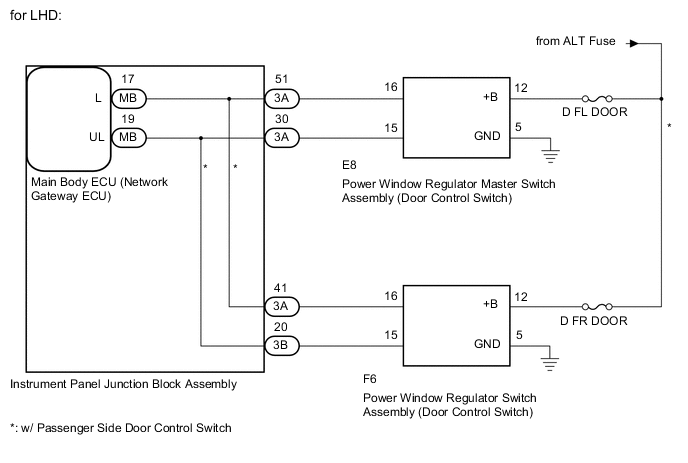
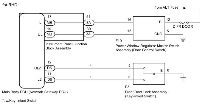
The main body ECU (network gateway ECU) receives switch signals from the door control switch, and driver side door key cylinder switch, activates the door lock motor on each door accordingly.
WIRING DIAGRAM
CAUTION / NOTICE / HINT
Note
Inspect the fuses for circuits related to this system before performing the following inspection procedure.
PROCEDURE
-
CHECK DOOR LOCK OPERATION
-
Proceed to the next step according to the symptom listed in the table below.
Result Result Proceed to Doors cannot be locked through power window regulator master switch assembly A Doors cannot be locked through power window regulator switch assembly*1 B Doors cannot be locked through driver side door key cylinder*2 C
-
*1: w/ Passenger Side Door Control Switch
-
*2: w/ Key-linked Switch
-
B 
READ VALUE USING GTS (DOOR LOCK SW-LOCK AND DOOR LOCK SW-UNLOCK) Click here
C
READ VALUE USING GTS (DOOR KEY SW-LOCK AND DOOR KEY SW-UNLOCK) Click here
A 
-
-
READ VALUE USING GTS (DOOR LOCK SW-LOCK AND DOOR LOCK SW-UNLOCK)
-
Connect the GTS to the DLC3.
-
Turn the ignition switch to ON.
-
Turn the GTS on.
-
Enter the following menus: Body Electrical / Main Body / Data List.
-
According to the display on the GTS, read the Data List.
Main Body Tester Display Measurement Item/Range Normal Condition Diagnostic Note Door Lock SW-Lock Door control switch (power window regulator master switch assembly) lock signal / OFF or ON OFF: Lock side of door control switch (power window regulator master switch assembly) not pushed
ON: Lock side of door control switch (power window regulator master switch assembly) pushed
- Door Lock SW-Unlock Door control switch (power window regulator master switch assembly) unlock signal / OFF or ON OFF: Unlock side of door control switch (power window regulator master switch assembly) not pushed
ON: Unlock side of door control switch (power window regulator master switch assembly) pushed
- OK When the switch is operating, the GTS should display as shown in the table.
OK 
REPLACE MAIN BODY ECU (NETWORK GATEWAY ECU) Click here
NG
-
-
INSPECT POWER WINDOW REGULATOR MASTER SWITCH ASSEMBLY
-
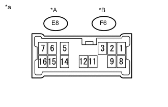
Text in Illustration *A for LHD *B for RHD *a Component with harness connected
(Power Window Regulator Master Switch Assembly (Door Control Switch))
Remove the power window regulator master switch assembly Click here.
-
Connect the E8*1 or F6*2 power window regulator master switch assembly connector.
-
*1: for LHD
-
*2: for RHD
-
-
Connect the cable to the negative(-) battery terminal.
-
Measure the voltage according to the value(s) in the table below.
Standard Voltage (for LHD) Tester Connection Switch Condition Specified Condition E8-16 - E8-5 (GND) Lock switch pushed 9.15 V or higher off Below 1 V E8-15 - E8-5 (GND) Unlock switch pushed 9.15 V or higher off Below 1 V Standard Voltage (for RHD) Tester Connection Switch Condition Specified Condition F6-16 - E8-5 (GND) Lock switch pushed 9.15 V or higher off Below 1 V F6-15 - E8-5 (GND) Unlock switch pushed 9.15 V or higher off Below 1 V
NG
REPLACE POWER WINDOW REGULATOR MASTER SWITCH ASSEMBLY Click here
OK
-
-
CHECK HARNESS AND CONNECTOR (POWER WINDOW MASTER SWITCH - JUNCTION BLOCK AND BODY GROUND)
-
for LHD:
-
Disconnect the 3A instrument panel junction block assembly connector.
-
Disconnect the E8 power window regulator master switch assembly (door control switch) connector.
-
Measure the resistance according to the value(s) in the table below.
Standard Resistance Tester Connection Condition Specified Condition 3A-51 - E8-16 Always Below 1 Ω 3A-30 - E8-15 Always Below 1 Ω E8-5 (GND) - Body ground Always Below 1 Ω 3A-51 or E8-16 - Body ground Always 10 kΩ or higher 3A-30 or E8-15 - Body ground Always 10 kΩ or higher
-
-
for RHD:
-
Disconnect the 3A instrument panel junction block assembly connector.
-
Disconnect the F6 power window regulator master switch assembly (door control switch) connector.
-
Measure the resistance according to the value(s) in the table below.
Standard Resistance Tester Connection Condition Specified Condition 3A-51 - F6-16 Always Below 1 Ω 3A-30 - F6-15 Always Below 1 Ω F6-5 (GND) - Body ground Always Below 1 Ω 3A-51 or F6-16 - Body ground Always 10 kΩ or higher 3A-30 or F6-15 - Body ground Always 10 kΩ or higher
-
NG
REPAIR OR REPLACE HARNESS OR CONNECTOR
OK
-
-
INSPECT INSTRUMENT PANEL JUNCTION BLOCK ASSEMBLY
-
Remove the instrument panel junction block assembly Click here.
-
Remove the main body ECU (network gateway ECU) from the instrument panel junction block assembly.
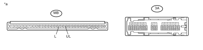
Text in Illustration *a Component without harness connected
(Instrument Panel Junction Block Assembly)
- - -
Measure the resistance according to the value(s) in the table below.
Standard Resistance Tester Connection Condition Specified Condition MB-17 (L) - 3A-51 Always Below 1 Ω MB-19 (UL) - 3A-30 Always Below 1 Ω
OK
REPLACE MAIN BODY ECU (NETWORK GATEWAY ECU) Click here
NG
REPLACE INSTRUMENT PANEL JUNCTION BLOCK ASSEMBLY Click here
-
-
READ VALUE USING GTS (DOOR LOCK SW-LOCK AND DOOR LOCK SW-UNLOCK)
-
Connect the GTS to the DLC3.
-
Turn the ignition switch to ON.
-
Turn the GTS on.
-
Enter the following menus: Body Electrical / Main Body / Data List.
-
According to the display on the GTS, read the Data List.
Main Body Tester Display Measurement Item/Range Normal Condition Diagnostic Note Door Lock SW-Lock Door control switch (power window regulator switch assembly) lock signal / OFF or ON OFF: Lock side of door control switch (power window regulator switch assembly) not pushed
ON: Lock side of door control switch (power window regulator switch assembly) pushed
- Door Lock SW-Unlock Door control switch (power window regulator switch assembly) unlock signal / OFF or ON OFF: Unlock side of door control switch (power window regulator switch assembly) not pushed
ON: Unlock side of door control switch (power window regulator switch assembly) pushed
- OK When the switch is operating, the GTS should display as shown in the table.
OK
REPLACE MAIN BODY ECU (NETWORK GATEWAY ECU) Click here
NG
-
-
INSPECT POWER WINDOW REGULATOR SWITCH ASSEMBLY
-
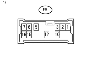
Text in Illustration *a Component with harness connected
(Power Window Regulator Switch Assembly (Door Control Switch))
Remove the power window regulator switch assembly Click here.
-
Connect the F6 power window regulator switch assembly connector.
-
Connect the cable to the negative(-) battery terminal.
-
Measure the voltage according to the value(s) in the table below.
Standard Voltage Tester Connection Switch Condition Specified Condition F6-16 - F6-5 (GND) Lock switch pushed 9.15 V or higher off Below 1 V F6-15 - F6-5 (GND) Unlock switch pushed 9.15 V or higher off Below 1 V
NG
REPLACE POWER WINDOW REGULATOR SWITCH ASSEMBLY Click here
OK
-
-
CHECK HARNESS AND CONNECTOR (POWER WINDOW SWITCH - JUNCTION BLOCK AND BODY GROUND)
-
Disconnect the 3A and 3B instrument panel junction block assembly connectors.
-
Disconnect the F6 power window regulator switch assembly (door control switch) connector.
-
Measure the resistance according to the value(s) in the table below.
Standard Resistance Tester Connection Condition Specified Condition 3A-41 - F6-16 Always Below 1 Ω 3B-20 - F6-15 Always Below 1 Ω F6-5 (GND) - Body ground Always Below 1 Ω 3A-41 or F6-16 - Body ground Always 10 kΩ or higher 3B-20 or F6-15 - Body ground Always 10 kΩ or higher
NG
REPAIR OR REPLACE HARNESS OR CONNECTOR
OK
-
-
INSPECT INSTRUMENT PANEL JUNCTION BLOCK ASSEMBLY
-
Remove the instrument panel junction block assembly Click here.
-
Remove the main body ECU (network gateway ECU) from the instrument panel junction block assembly.
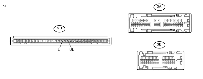
Text in Illustration *a Component without harness connected
(Instrument Panel Junction Block Assembly)
- - -
Measure the resistance according to the value(s) in the table below.
Standard Resistance Tester Connection Condition Specified Condition MB-17 (L) - 3A-41 Always Below 1 Ω MB-19 (UL) - 3B-20 Always Below 1 Ω
OK
REPLACE MAIN BODY ECU (NETWORK GATEWAY ECU) Click here
NG
REPLACE INSTRUMENT PANEL JUNCTION BLOCK ASSEMBLY Click here
-
-
READ VALUE USING GTS (DOOR KEY SW-LOCK AND DOOR KEY SW-UNLOCK)
-
Connect the GTS to the DLC3.
-
Turn the ignition switch to ON.
-
Turn the GTS on.
-
Enter the following menus: Body Electrical / Main Body / Data List.
-
According to the display on the GTS, read the Data List.
Main Body Tester Display Measurement Item/Range Normal Condition Diagnostic Note Door Key SW-Lock Door key-linked lock switch signal/ ON or OFF ON: Driver side door side key cylinder is turned to lock position
OFF: Driver side door key cylinder is turned to unlock position
- Door Key SW-ULock Door key-linked unlock switch signal/ ON or OFF ON: Driver side door key cylinder is turned to unlock position
OFF: Driver side door key cylinder is turned to lock position
- OK ON (driver side door key cylinder is turned to lock/unlock position) appears on the tester screen.
OK
REPLACE MAIN BODY ECU (NETWORK GATEWAY ECU) Click here
NG
-
-
INSPECT FRONT DOOR LOCK ASSEMBLY RH
-
Remove the front door lock assembly RH Click here.
-
Inspect the front door lock assembly RH Click here.
NG
REPLACE FRONT DOOR LOCK ASSEMBLY RH Click here
OK
-
-
CHECK HARNESS AND CONNECTOR (MAIN BODY ECU - FRONT DOOR LOCK AND BODY GROUND)
-
Disconnect the D5 main body ECU (network gateway ECU) connector.
-
Disconnect the F3 front door lock assembly RH connector.
-
Measure the resistance according to the value(s) in the table below.
Standard Resistance Tester Connection Condition Specified Condition D5-12 (UL2) - F3-5 Always Below 1 Ω D5-11 (L2) - F3-6 Always Below 1 Ω F3-8 (E) - Body ground Always Below 1 Ω D5-12 (UL2) or F3-5 - Body ground Always 10 kΩ or higher D5-11 (L2) or F3-6 - Body ground Always 10 kΩ or higher
OK
REPLACE MAIN BODY ECU (NETWORK GATEWAY ECU) Click here
NG
REPAIR OR REPLACE HARNESS OR CONNECTOR
-