CAN COMMUNICATION SYSTEM TERMINALS OF ECU
Note
-
After turning the ignition switch off, waiting time may be required before disconnecting the cable from the negative (-) battery terminal. Therefore, make sure to read the disconnecting the cable from the negative (-) battery terminal notices before proceeding with work Click here.
-
Turn the ignition switch off before measuring the resistances between CAN main bus lines and between CAN branch lines.
-
Turn the ignition switch off before inspecting CAN bus lines for a ground short.
-
Before measuring the resistance, leave the vehicle as is for at least 1 minute and do not operate the ignition switch, any other switches or the doors. If any doors need to be opened in order to check connectors, open the doors and leave them open.
-
This section describes the standard values for all CAN related components.
Tech Tips
-
Operating the ignition switch, any other switches or a door triggers the related ECU and sensor communication on the CAN. This communication will cause the resistance value to change.
-
Even after DTCs are cleared, if a DTC is stored again after driving the vehicle for a while, the malfunction may be occurring due to vibration of the vehicle. In such a case, wiggling the ECUs or wire harness while performing the inspection below may help determine the cause of the malfunction.
-
CAN NO. 1 JUNCTION CONNECTOR (for RHD)
-
Check the CAN No. 1 junction connector.
Tech Tips
The following tables contain information about the items and buses connected via junction connectors. The junction connector may be used for multiple separate buses. In this case, the name of the bus will be shown below the name of the item that terminals are connected to. The bus name will be shown in brackets (example: (for V bus)).
-
Connection diagram
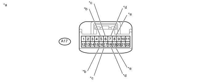
Text in Illustration *a Front view of wire harness connector
(to CAN No. 1 Junction Connector)
*b to TCM*
(for V bus)
*c to CAN No. 2 Junction Connector
(for V bus)
*d to ECM
(for V bus)
*e to Power Steering ECU Assembly
(for V bus)
- - -
Check the connection diagram of the components which are connected to the CAN No. 1 junction connector.
Terminal No. Wiring Color Connected to A17-5 B-W TCM*
(for V bus)
A17-16 L A17-6 W-B CAN No. 2 Junction Connector
(for V bus)
A17-17 R-Y A17-7 O ECM
(for V bus)
A17-18 B-P A17-8 B Power Steering ECU Assembly
(for V bus)
A17-19 W
-
* : for Automatic Transmission System
-
-
CAN NO. 1 JUNCTION CONNECTOR (for LHD)
-
Check the CAN No. 1 junction connector.
-
Connection diagram
Text in Illustration *a Front view of wire harness connector
(to CAN No. 1 Junction Connector)
*b to TCM*
(for V bus
*c to Skid Control ECU (Brake Actuator Assembly)
(for V bus)
*d to CAN No. 2 Junction Connector
(for V bus)
*e to Power Steering ECU Assembly
(for V bus)
- - -
Check the connection diagram of the components which are connected to the CAN No. 1 junction connector.
Terminal No. Wiring Color Connected to A17-5 B-W TCM*
(for V bus)
A17-16 L A17-6 BR Skid Control ECU (Brake Actuator Assembly)
(for V bus)
A17-17 B-R A17-7 W-B CAN No. 2 Junction Connector
(for V bus)
A17-18 R-Y A17-8 B Power Steering ECU Assembly
(for V bus)
A17-19 W
-
* : for Automatic Transmission System
* : for Automatic Transmission System
-
-
CAN NO. 2 JUNCTION CONNECTOR (for RHD)
-
Check the CAN No. 2 junction connector.
-
Connection diagram
Text in Illustration *a Front view of wire harness connector
(to CAN No. 2 Junction Connector)
*b to Skid Control ECU (Brake Actuator Assembly)
(for V bus)
*c to Combination Meter Assembly
(for V bus)
*d to Main Body ECU (Network Gateway ECU)
(for V bus)
*e to Certification ECU (Smart Key ECU Assembly)*1
(for V bus)
*f to DLC3
(for V bus)
*g to Steering Angle Sensor (Spiral Cable Sub-assembly)
(for V bus)
*h to PSP (Option Connector)
(for V bus)
*i to Air Bag ECU Assembly
(for V bus)
*j to CAN No. 1 Junction Connector
(for V bus)
*k to Air Conditioning Control Assembly*2
(for V bus)
- - -
Check the connection diagram of the components which are connected to the CAN No. 2 junction connector.
Terminal No. Wiring Color Connected to D43-1 W-B CAN No. 1 Junction Connector
(for V bus)
D43-12 R-Y D43-2 BR Combination Meter Assembly
(for V bus)
D43-13 BR-W D43-3 P Main Body ECU (Network Gateway ECU)
(for V bus)
D43-14 LG D43-4 G Certification ECU (Smart Key ECU Assembly)*1
(for V bus)
D43-15 R D43-5 B-Y DLC3
(for V bus)
D43-16 LG D43-6 G-W Steering Angle Sensor (Spiral Cable Sub-assembly)
(for V bus)
D43-17 G D43-7 P PSP (Option Connector)
(for V bus)
D43-18 L D43-8 P-L Air Bag ECU Assembly
(for V bus)
D43-19 R-W D43-9 O CAN No. 1 Junction Connector
(for V bus)
D43-20 B-P D43-10 L-W Air Conditioning Control Assembly*2
(for V bus)
D43-21 L-Y
-
*1 : w/ Entry and Start System
*2 : for Automatic Air Conditioning System
-
-
CAN NO. 2 JUNCTION CONNECTOR (for LHD)
-
Check the CAN No. 2 junction connector.
-
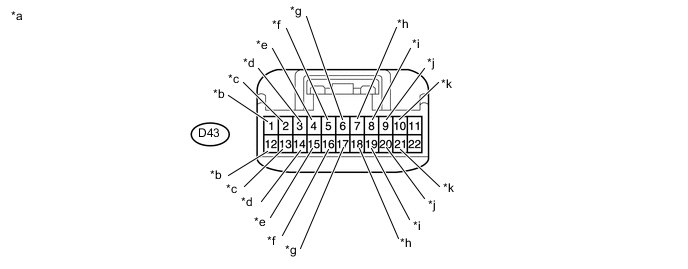
Connection diagram
Text in Illustration *a Front view of wire harness connector
(to CAN No. 2 Junction Connector)
*b to CAN No. 1 Junction Connector
(for V bus)
*c to Combination Meter Assembly
(for V bus)
*d to Main Body ECU (Network Gateway ECU)
(for V bus)
*e to Certification ECU (Smart Key ECU Assembly)*1
(for V bus)
*f to DLC3
(for V bus)
*g to Steering Angle Sensor (Spiral Cable Sub-assembly)
(for V bus)
*h to PSP (Option Connector)
(for V bus)
*i to Air Bag ECU Assembly
(for V bus)
*j to ECM
(for V bus)
*k to Air Conditioning Control Assembly*2
(for V bus)
- - -
Check the connection diagram of the components which are connected to the CAN No. 2 junction connector.
Terminal No. Wiring Color Connected to D43-1 W-B CAN No. 1 Junction Connector
(for V bus)
D43-12 R-Y D43-2 BR Combination Meter Assembly
(for V bus)
D43-13 BR-W D43-3 P Main Body ECU (Network Gateway ECU)
(for V bus)
D43-14 LG D43-4 G Certification ECU (Smart Key ECU Assembly)*1
(for V bus)
D43-15 R D43-5 B-Y DLC3
(for V bus)
D43-16 LG D43-6 G-W Steering Angle Sensor (Spiral Cable Sub-assembly)
(for V bus)
D43-17 G D43-7 P PSP (Option Connector)
(for V bus)
D43-18 L D43-8 P-L Air Bag ECU Assembly
(for V bus)
D43-19 R-W D43-9 O ECM
(for V bus)
D43-20 B-P D43-10 L-W Air Conditioning Control Assembly*2
(for V bus)
D43-21 L-Y
-
*1 : w/ Entry and Start System
*2 : for Automatic Air Conditioning System
-
-
DLC3
-
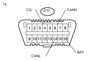
Text in Illustration *a DLC3 Measure the resistance according to the value(s) in the table below.
-
-
ECM
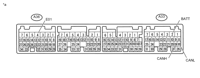
Text in Illustration *a Component without harness connected
(ECM)
- -
-
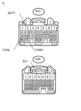
Text in Illustration *a Front view of wire harness connector
(to ECM)
Disconnect the A33 and A36 ECM connectors.
-
Measure the resistance according to the value(s) in the table below.
-
-
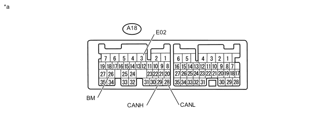
TCM (for Automatic Transmission System)
Text in Illustration *a Component without harness connected
(TCM)
- -
-
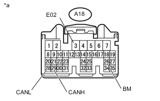
Text in Illustration *a Front view of wire harness connector
(to TCM)
Disconnect the A18 TCM connector.
-
Measure the resistance according to the value(s) in the table below.
-
-
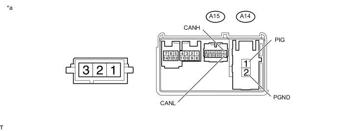
POWER STEERING ECU ASSEMBLY
Text in Illustration *a Component without harness connected
(Power Steering ECU Assembly)
- -
-
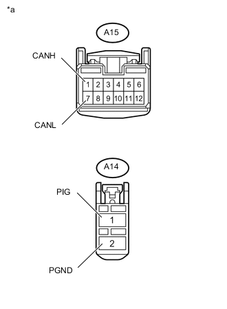
Text in Illustration *a Front view of wire harness connector
(to Power Steering ECU Assembly)
Disconnect the A14 and A15 power steering ECU assembly connectors.
-
Measure the resistance according to the value(s) in the table below.
-
-
COMBINATION METER ASSEMBLY
Text in Illustration *a Component without harness connected
(Combination Meter Assembly)
- -
-
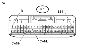
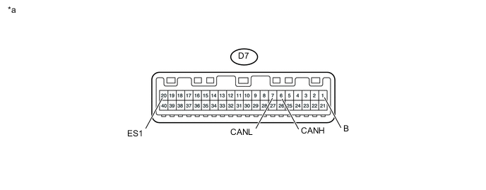
Text in Illustration *a Front view of wire harness connector
(to Combination Meter Assembly)
Disconnect the D7 combination meter assembly connector.
-
Measure the resistance according to the value(s) in the table below.
-
-
INSTRUMENT PANEL JUNCTION BLOCK ASSEMBLY AND MAIN BODY ECU (NETWORK GATEWAY ECU)
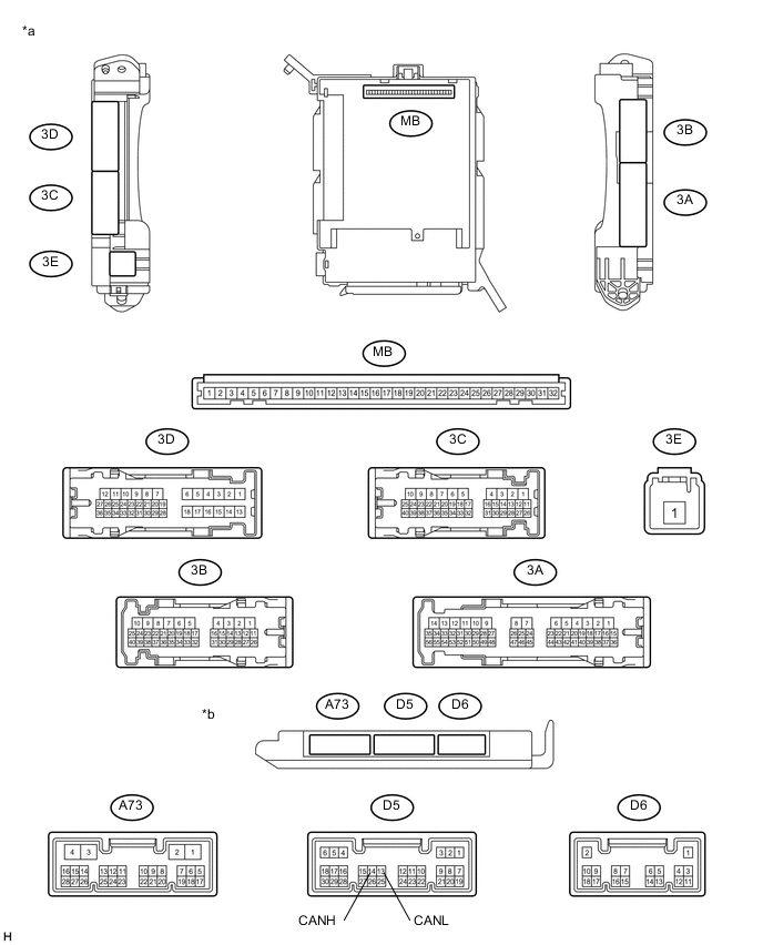
Text in Illustration *a Component without harness connected
(Instrument Panel Junction Block Assembly)
*b Component without harness connected
(Main Body ECU (Network Gateway ECU))
-
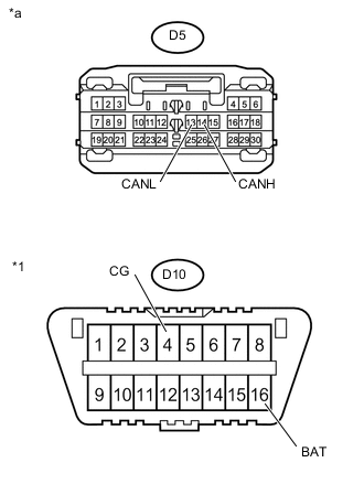
Text in Illustration *1 DLC3 *a Front view of wire harness connector
(to Main Body ECU (Network Gateway ECU))
Disconnect the D5 main body ECU (network gateway ECU) connector.
-
Measure the resistance according to the value(s) in the table below.
-
-
CERTIFICATION ECU (SMART KEY ECU ASSEMBLY) (w/ Entry and Start System)
Text in Illustration *a Component without harness connected
(Certification ECU (Smart Key ECU Assembly))
- -
-
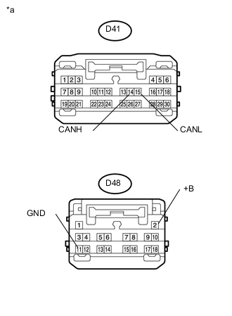
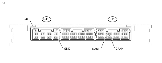
Text in Illustration *a Front view of wire harness connector
(to Certification ECU (Smart Key ECU Assembly))
Disconnect the D41 and D48 certification ECU (smart key ECU assembly) connectors.
-
Measure the resistance according to the value(s) in the table below.
-
-
STEERING ANGLE SENSOR (SPIRAL CABLE SUB-ASSEMBLY)
Text in Illustration *a Component without harness connected
(Steering Angle Sensor (Spiral Cable Sub-assembly))
- -
-
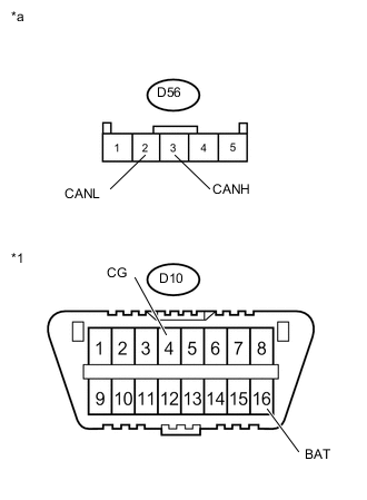
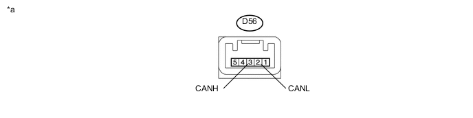
Text in Illustration *1 DLC3 *a Front view of wire harness connector
(to Steering Angle Sensor (Spiral Cable Sub-assembly))
Disconnect the D56 steering angle sensor (spiral cable sub-assembly) connector.
-
Measure the resistance according to the value(s) in the table below.
-
-
PSP (OPTION CONNECTOR)
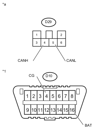
Text in Illustration *1 DLC3 *a Front view of wire harness connector
(to PSP (Option Connector))
-
Measure the resistance according to the value(s) in the table below.
-
-
AIR BAG ECU ASSEMBLY
Text in Illustration *a Component without harness connected
(Air Bag ECU Assembly)
- -
-
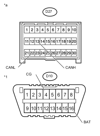
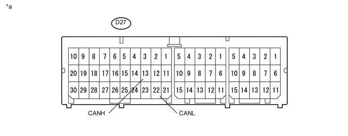
Text in Illustration *1 DLC3 *a Front view of wire harness connector
(to Air Bag ECU Assembly)
Disconnect the D27 air bag ECU assembly connector.
-
Measure the resistance according to the value(s) in the table below.
-
-
AIR CONDITIONING CONTROL ASSEMBLY (for Automatic Air Conditioning System)
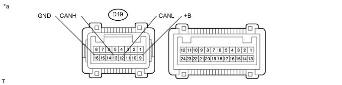
Text in Illustration *a Component without harness connected
(Air Conditioning Control Assembly)
- -
-
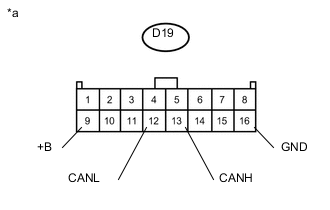
Text in Illustration *a Front view of wire harness connector
(to Air Conditioning Control Assembly)
Disconnect the D19 air conditioning control assembly connector.
-
Measure the resistance according to the value(s) in the table below.
-
-
SKID CONTROL ECU (BRAKE ACTUATOR ASSEMBLY)
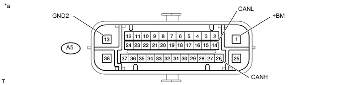
Text in Illustration *a Component without harness connected
(Skid Control ECU (Brake Actuator Assembly))
- -
-
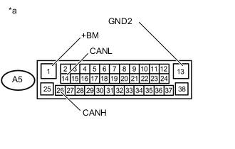
Text in Illustration *a Front view of wire harness connector
(to Skid Control ECU (Brake Actuator Assembly))
Disconnect the A5 skid control ECU (brake actuator assembly) connector.
-
Measure the resistance according to the value(s) in the table below.
-