CAN COMMUNICATION SYSTEM SYSTEM DIAGRAM
-
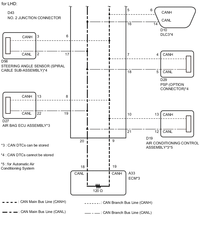
OVERALL CAN BUS DIAGRAM
-
Control system CAN is composed of 1 bus.
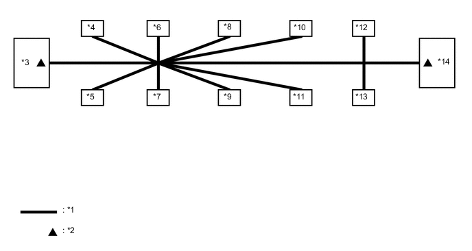
Text in Illustration *1 V Bus *2 V Bus Terminating Resistor *3 Skid Control ECU (Brake Actuator Assembly) (for RHD)
ECM (for LHD)
(for V Bus)
*4 Combination Meter Assembly
(for V Bus)
*5 Main Body ECU (Network Gateway ECU)
(for V Bus)
*6 Certification ECU (Smart Key ECU Assembly)
(for V Bus)
*7 DLC3
(for V Bus)
*8 Steering Angle Sensor (Spiral Cable Sub-assembly)
(for V Bus)
*9 PSP (Option Connector)
(for V Bus)
*10 Air Bag ECU Assembly
(for V Bus)
*11 Air Conditioning Control Assembly
(for V Bus)
*12 TCM
(for V Bus)
*13 Power Steering ECU Assembly
(for V Bus)
*14 ECM (for RHD)
Skid Control ECU (Brake Actuator Assembly) (for LHD)
(for V Bus)
-
-
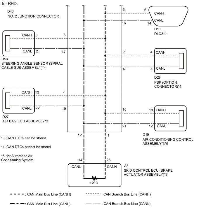
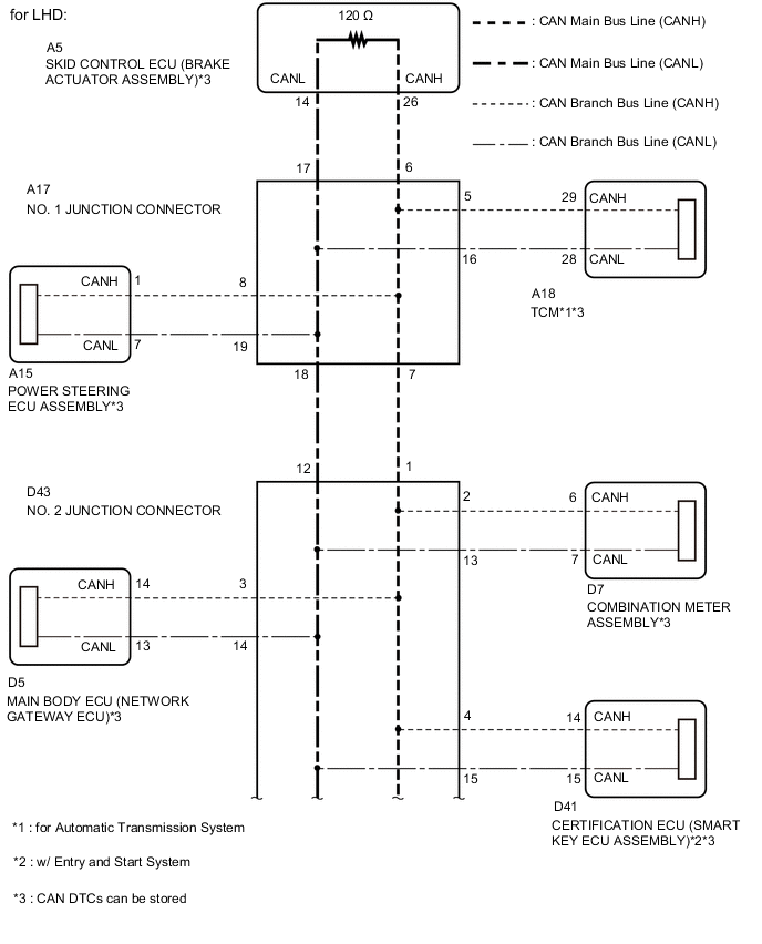
V BUS
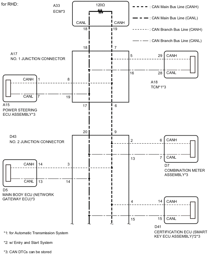
Tech Tips
The CAN communication system connects to other networks via ECUs that function as a gateway Click here.