WIRELESS DOOR LOCK CONTROL SYSTEM(w/o Entry and Start System), Diagnostic DTC:B1242
| DTC Code | DTC Name |
|---|---|
| B1242 | Wireless Door Lock Tuner Circuit Malfunction |
DESCRIPTION
-
This door control receiver receives signals from the transmitter and sends these signals to the main body ECU (network gateway ECU).
w/o Tire Pressure Warning System
-
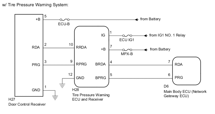
The door control receiver receives signals from the door control transmitter and sends these signals to the main body ECU (network gateway ECU) via the tire pressure warning ECU and receiver.
w/ Tire Pressure Warning System
| DTC No. | DTC Detection Condition | Trouble Area |
|---|---|---|
| B1242 | In diagnostic mode, applicable RDA signal cannot be received 3 times in succession after the PRG signal is output from the main body ECU (network gateway ECU). |
|
-
*: w/ Tire Pressure Warning System
WIRING DIAGRAM
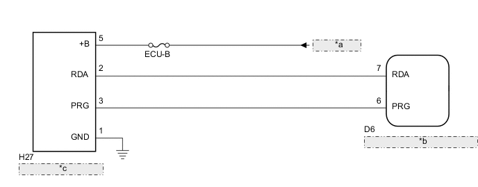
| *a | from Battery |
| *b | Main Body ECU (Network Gateway ECU) |
| *c | Door Control Receiver |
CAUTION / NOTICE / HINT
Note
-
Inspect the fuses for circuits related to this system before performing the following inspection procedure.
-
When replacing or inspecting the door control receiver and wire harness, do not change the position or length of the wire harness. If the wire harness is too close to the door control receiver, wireless function performance may be affected.
-
* When replacing the tire pressure warning ECU and receiver, read the transmitter IDs stored in the old ECU using the GTS and write them down before removal.
-
* It is necessary to perform initialization after registration of the transmitter IDs into the tire pressure warning ECU and receiver if the tire pressure warning ECU and receiver has been replaced.
-
for Initialization Click here
-
for Registration Click here
-
*: w/ Tire Pressure Warning System
PROCEDURE
-
CONFIRM VEHICLE SPECIFICATION
-
Confirm the vehicle specification.
Result Result Proceed to w/ Tire Pressure Warning System A w/o Tire Pressure Warning System B
B 
CHECK HARNESS AND CONNECTOR (MAIN BODY ECU (NETWORK GATEWAY ECU) - DOOR CONTROL RECEIVER) Click here
A 
-
-
CHECK FOR DTC (TIRE PRESSURE WARNING SYSTEM)
-
Clear the DTCs Click here.
-
Check for DTCs Click here.
OK DTCs are not output. Result Result Proceed to NG A OK B
A 
GO TO TIRE PRESSURE WARNING SYSTEM Click here
B
CHECK HARNESS AND CONNECTOR (MAIN BODY ECU (NETWORK GATEWAY ECU) - TIRE PRESSURE WARNING ECU AND RECEIVER) Click here
-
-
CHECK HARNESS AND CONNECTOR (MAIN BODY ECU (NETWORK GATEWAY ECU) - DOOR CONTROL RECEIVER)
-
Disconnect the D6 main body ECU (network gateway ECU) connector.
-
Disconnect the H27 door control receiver connector.
-
Measure the resistance according to the value(s) in the table below.
Standard Resistance (Check for Open) Tester Connection Condition Specified Condition D6-6 (PRG) - H27-3 (PRG) Always Below 1 Ω D6-7 (RDA) - H27-2 (RDA) Always Below 1 Ω Standard Resistance (Check for Short) Tester Connection Condition Specified Condition D6-6 (PRG) or H27-3 (PRG) - Body ground Always 10 kΩ or higher D6-7 (RDA) or H27-2 (RDA) - Body ground Always 10 kΩ or higher
NG
REPAIR OR REPLACE HARNESS OR CONNECTOR
OK
-
-
INSPECT DOOR CONTROL RECEIVER (POWER SOURCE, GROUND)
-
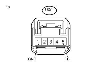
Text in Illustration *a Front view of wire harness connector
(to Door Control Receiver)
Measure the voltage and resistance according to the value(s) in the table below.
Standard Voltage Tester Connection Condition Specified Condition H27-5 (+B) - Body ground Always 11 to 14 V Standard Resistance Tester Connection Condition Specified Condition H27-1 (GND) - Body ground Always Below 1 Ω
NG
REPAIR OR REPLACE HARNESS OR CONNECTOR
OK
-
-
REPLACE DOOR CONTROL RECEIVER
-
Replace the door control receiver with a new one Click here.
NEXT
-
-
REGISTER RECOGNITION CODE
-
Perform the Registration procedures Click here.
NEXT
-
-
CHECK FOR DTC
-
Clear the DTC Click here.
-
Check for DTC Click here.
OK DTC is not output.
OK
END (DOOR CONTROL RECEIVER IS DEFECTIVE)
NG
REPLACE MAIN BODY ECU (NETWORK GATEWAY ECU) Click here
-
-
CHECK HARNESS AND CONNECTOR (MAIN BODY ECU (NETWORK GATEWAY ECU) - TIRE PRESSURE WARNING ECU AND RECEIVER)
-
Disconnect the D6 main body ECU (network gateway ECU) connector.
-
Disconnect the H28 tire pressure warning ECU and receiver connector.
-
Measure the resistance according to the value(s) in the table below.
Standard Resistance (Check for Open) Tester Connection Condition Specified Condition D6-7 (RDA) - H28-4 (BRDA) Always Below 1 Ω D6-6 (PRG) - H28-5 (BPRG) Always Below 1 Ω Standard Resistance (Check for Short) Tester Connection Condition Specified Condition D6-7 (RDA) or H28-4 (BRDA) - Body ground Always 10 kΩ or higher D6-6 (PRG) or H28-5 (BPRG) - Body ground Always 10 kΩ or higher
NG
REPAIR OR REPLACE HARNESS OR CONNECTOR
OK
-
-
CHECK HARNESS AND CONNECTOR (TIRE PRESSURE WARNING ECU AND RECEIVER - DOOR CONTROL RECEIVER)
-
Disconnect the H28 tire pressure warning ECU and receiver connector.
-
Disconnect the H27 door control receiver connector.
-
Measure the resistance according to the value(s) in the table below.
Standard Resistance (Check for Open) Tester Connection Condition Specified Condition H28-10 (RRDA) - H27-2 (RDA) Always Below 1 Ω H28-9 (RPRG) - H27-3 (PRG) Always Below 1 Ω Standard Resistance (Check for Short) Tester Connection Condition Specified Condition H28-10 (RRDA) or H27-2 (RDA) - Body ground Always 10 kΩ or higher H28-9 (RPRG) or H27-3 (PRG) - Body ground Always 10 kΩ or higher
NG
REPAIR OR REPLACE HARNESS OR CONNECTOR
OK
-
-
INSPECT DOOR CONTROL RECEIVER (POWER SOURCE, GROUND)
-
Text in Illustration *a Front view of wire harness connector
(to Door Control Receiver)
Measure the voltage and resistance according to the value(s) in the table below.
Standard Voltage Tester Connection Condition Specified Condition H27-5 (+B) - Body ground Always 11 to 14 V Standard Resistance Tester Connection Condition Specified Condition H27-1 (GND) - Body ground Always Below 1 Ω
NG
REPAIR OR REPLACE HARNESS OR CONNECTOR
OK
-
-
INSPECT TIRE PRESSURE WARNING ECU AND RECEIVER (POWER SOURCE, GROUND)
-
Disconnect the H28 tire pressure warning ECU and receiver connector.
-
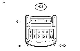
Text in Illustration *a Front view of wire harness connector
(to Tire Pressure Warning ECU and Receiver)
Measure the resistance and voltage according to the value(s) in the table below.
Standard Voltage Tester Connection Condition Specified Condition H28-1 (IG) - Body ground Ignition switch ON 11 to 14 V H28-7 (+B) - Body ground Always 11 to 14 V Standard Resistance Tester Connection Condition Specified Condition H28-12 (GND) - Body ground Always Below 1 Ω
NG
REPAIR OR REPLACE HARNESS OR CONNECTOR
OK
-
-
REPLACE DOOR CONTROL RECEIVER
-
Replace the door control receiver with a new one Click here.
NEXT
-
-
REGISTER RECOGNITION CODE
-
Perform the Registration procedures Click here.
NEXT
-
-
CHECK FOR DTC
-
Clear the DTC Click here.
-
Check for DTC Click here.
OK DTC is not output.
OK
END (DOOR CONTROL RECEIVER IS DEFECTIVE)
NG
-
-
REPLACE TIRE PRESSURE WARNING ECU AND RECEIVER
-
Replace the tire pressure warning ECU and receiver with a new one Click here.
NEXT
-
-
CHECK FOR DTC
-
Clear the DTC Click here.
-
Check for DTC Click here.
OK DTC is not output.
OK
END (TIRE PRESSURE WARNING ECU AND RECEIVER IS DEFECTIVE)
NG
REPLACE MAIN BODY ECU (NETWORK GATEWAY ECU) Click here
-