ELECTRIC POWER CONTROL SYSTEM, Diagnostic DTC:B1011
| DTC Code | DTC Name |
|---|---|
| B1011 | Battery Power Supply Control Circuit |
DESCRIPTION
-
B1011 is stored when a malfunction is detected in the BMPX circuit.
Tech Tips
In some cases, none of the functions of the main body ECU (network gateway ECU) may function when B1012 is stored together with B1011.
| DTC No. | DTC Detection Condition | Trouble Area |
|---|---|---|
| B1011 | When BMPX voltage is 8.3 V or less, or 16.7 V or more (BMPX circuit malfunction) |
|
WIRING DIAGRAM
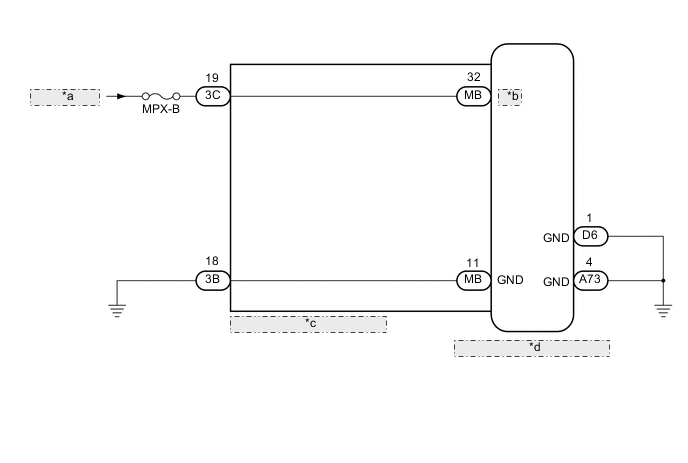
| *a | from Battery |
| *b | BMPX |
| *c | Instrument Panel Junction Block Assembly |
| *d | Main Body ECU (Network Gateway ECU) |
CAUTION / NOTICE / HINT
Note
Inspect the fuses for circuits related to this system before performing the following inspection procedure.
PROCEDURE
-
CLEAR DTC
-
Clear the DTCs Click here.
NEXT 
-
-
CHECK FOR DTC
-
Check for DTCs Click here.
Result Result Proceed to DTC B1011 is output A DTC is not output B
B 
USE SIMULATION METHOD TO CHECK Click here
A
-
-
CHECK HARNESS AND CONNECTOR (BMPX VOLTAGE)
-
Disconnect the 3C instrument panel junction block assembly connector.
-
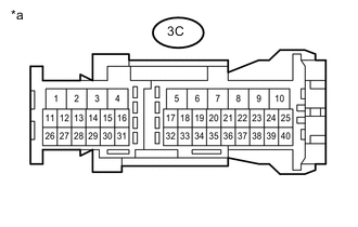
Text in Illustration *a Front view of wire harness connector
(to Instrument Panel Junction Block Assembly)
Measure the voltage according to the value(s) in the table below.
Standard Voltage Tester Connection Condition Specified Condition 3C-19 - Body ground Always 11 to 14 V
NG
REPAIR OR REPLACE HARNESS OR CONNECTOR
OK
-
-
CHECK HARNESS AND CONNECTOR (ECU GROUND)
-
Disconnect the D6 and A73 main body ECU (network gateway ECU) connector.
-
Disconnect the 3B instrument panel junction block assembly connector.
-
Measure the resistance according to the value(s) in the table below.
Standard Resistance Tester Connection Condition Specified Condition D6-1 (GND) - Body ground Always Below 1 Ω A73-4 (GND) - Body ground Always Below 1 Ω 3B-18 - Body ground Always Below 1 Ω
NG
REPAIR OR REPLACE HARNESS OR CONNECTOR
OK
-
-
INSPECT INSTRUMENT PANEL JUNCTION BLOCK ASSEMBLY
-
Remove the instrument panel junction block assembly Click here.
-
Remove the main body ECU (network gateway ECU) from the instrument panel junction block assembly.
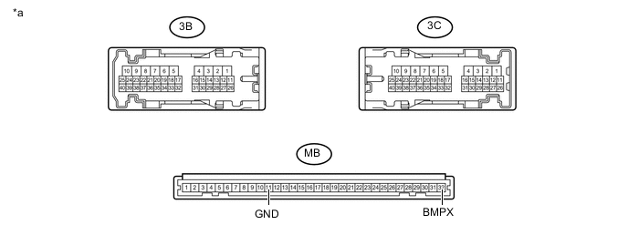
Text in Illustration *a Component without harness connected
(Instrument Panel Junction Block Assembly)
- - -
Measure the resistance according to the value(s) in the table below.
Standard Resistance Tester Connection Condition Specified Condition 3C-19 - MB-32 (BMPX) Always Below 1 Ω 3B-18 - MB-11 (GND) Always Below 1 Ω
OK
REPLACE MAIN BODY ECU (NETWORK GATEWAY ECU) Click here
NG
REPLACE INSTRUMENT PANEL JUNCTION BLOCK ASSEMBLY Click here
-