ELECTRIC POWER CONTROL SYSTEM, Diagnostic DTC:B1013
| DTC Code | DTC Name |
|---|---|
| B1013 | IG Power Supply Circuit |
DESCRIPTION
-
B1013 is stored when a malfunction is detected in the IG circuit.
| DTC No. | DTC Detection Condition | Trouble Area |
|---|---|---|
| B1013 | When IG voltage is 8.3 V or less, or 16.7 V or more (IG circuit malfunction) |
|
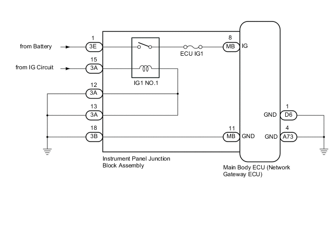
WIRING DIAGRAM
CAUTION / NOTICE / HINT
Note
Inspect the fuses for circuits related to this system before performing the following inspection procedure.
PROCEDURE
-
CLEAR DTC
-
Clear the DTCs Click here.
NEXT 
-
-
CHECK FOR DTC
-
Check for DTCs Click here.
Result Result Proceed to DTC B1013 is output A DTC is not output B
B 
USE SIMULATION METHOD TO CHECK Click here
A
-
-
CHECK HARNESS AND CONNECTOR (VOLTAGE)
-
Disconnect the 3A and 3E instrument panel junction block assembly connector.
-
Measure the voltage according to the value(s) in the table below.
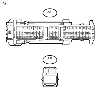
Standard Voltage Tester Connection Condition Specified Condition 3A-15 - Body ground Ignition switch ON 11 to 14 V 3E-1 - Body ground Always 11 to 14 V Text in Illustration *a Front view of wire harness connector
(to Instrument Panel Junction Block Assembly)
NG
REPAIR OR REPLACE HARNESS OR CONNECTOR
OK
-
-
CHECK HARNESS AND CONNECTOR (GROUND)
-
Disconnect the D6 and A73 main body ECU (network gateway ECU) connector.
-
Disconnect the 3A and 3B instrument panel junction block assembly connector.
-
Measure the resistance according to the value(s) in the table below.
Standard Resistance Tester Connection Condition Specified Condition D6-1 (GND) - Body ground Always Below 1 Ω A73-4 (GND) - Body ground Always Below 1 Ω 3A-12 - Body ground Always Below 1 Ω 3A-13 - Body ground Always Below 1 Ω 3B-18 - Body ground Always Below 1 Ω
NG
REPAIR OR REPLACE HARNESS OR CONNECTOR
OK
-
-
INSPECT INSTRUMENT PANEL JUNCTION BLOCK ASSEMBLY
-
Remove the instrument panel junction block assembly Click here.
-
Remove the main body ECU (network gateway ECU) from the instrument panel junction block assembly.
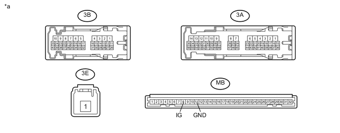
Text in Illustration *a Component without harness connected
(Instrument Panel Junction Block Assembly)
- - -
Measure the resistance according to the value(s) in the table below.
Standard Resistance Tester Connection Condition Specified Condition 3E-1 - MB-8 (IG) No battery voltage is applied across terminals 3A-15 and 3A-12 10 kΩ or higher 3E-1 - MB-8 (IG) Battery voltage is applied across terminals 3A-15 and 3A-12 Below 1 Ω 3B-18 - MB-11 (GND) Always Below 1 Ω
OK
REPLACE MAIN BODY ECU (NETWORK GATEWAY ECU) Click here
NG
REPLACE INSTRUMENT PANEL JUNCTION BLOCK ASSEMBLY Click here
-