GENERATOR INSPECTION

PROCEDURE
-
INSPECT BRUSH
-
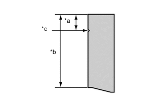
Text in Illustration *a Minimum length *b Standard length *c Mark of minimum length 
Brush Using a vernier caliper, measure the brush length.
Standard length 22.5 mm (0.885 in) Minimum length 5.0 mm (0.196 in) If the brush length is less than the minimum, replace the brush.
-
-
INSPECT GENERATOR COIL ASSEMBLY
-
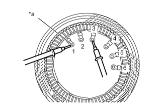
Text in Illustration *a Lead wire Check the resistance.
-
Measure the resistance according to the value(s) in the table below.
Standard Resistance Tester Connection Condition Specified Condition 1 - 2 Always Below 1 Ω 1 - 3 2 - 3 4 - 5 4 - 6 5 - 6 If the result is not as specified, replace the generator coil assembly.
-
-
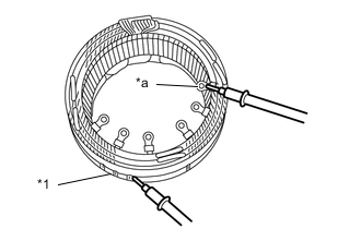
Text in Illustration *1 Stator core *a Lead wire Check the resistance.
-
Measure the resistance according to the value(s) in the table below.
Standard Resistance Tester Connection Condition Specified Condition Stator core - Lead wire Always 10 kΩ or higher If the result is not as specified, replace the generator coil assembly.
-
-
-
INSPECT GENERATOR ROTOR ASSEMBLY
-
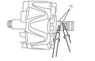
Text in Illustration *1 Slip Ring Check the generator rotor assembly for open circuits.
-
Measure the resistance according to the value(s) in the table below.
Standard Resistance Tester Connection Condition Specified Condition Slip ring - Slip ring 20°C (68°F) 2.0 to 2.4 Ω If the result is not as specified, replace the generator rotor assembly.
-
-
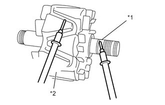
Text in Illustration *1 Slip Ring *2 Rotor Core Check if the generator rotor assembly is grounded.
-
Measure the resistance according to the value(s) in the table below.
Standard Resistance Tester Connection Condition Specified Condition Slip ring - Rotor core Always 10 kΩ or higher If the result is not as specified, replace the generator rotor assembly.
-
-
Check the slip ring diameter.
-
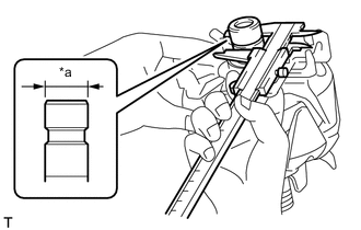
Text in Illustration *a Diameter of Slip Ring Using a vernier caliper, measure the diameter of each slip ring.
Standard diameter 22.7 mm (0.893 in.) Minimum diameter 22.1 mm (0.870 in.) If the diameter is less than the minimum, replace the generator rotor assembly.
-
-
-
INSPECT GENERATOR HOLDER WITH RECTIFIER
-
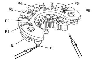
Check the resistance.
-
Measure the resistance according to the value(s) in the table below.
Standard Resistance Tester Connection Condition Specified Condition P1, P2, P3, P4, P5, P6 - B P1, P2, P3, P4, P5, P6 (Tester positive)
B (Tester negative)
Below 1 Ω P1, P2, P3, P4, P5, P6 (Tester negative)
B (Tester positive)
10 kΩ or higher P1, P2, P3, P4, P5, P6 - E P1, P2, P3, P4, P5, P6 (Tester positive)
E (Tester negative)
10 kΩ or higher P1, P2, P3, P4, P5, P6 (Tester negative)
E (Tester positive)
Below 1 Ω If the result is not as specified, replace the generator holder with rectifier.
-
-