CHARGING SYSTEM, Diagnostic DTC:P1530, P1531, P1532
| DTC Code | DTC Name |
|---|---|
| P1530 | Short in Battery Current Sensor Circuit |
| P1531 | Open in Battery Current Sensor Circuit |
| P1532 | Battery Current Sensor Circuit |
DESCRIPTION
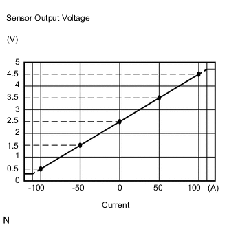
The battery current sensor assembly installed on the negative (-) battery terminal detects the amount of current supplied from the generator.
The battery current sensor assembly changes current to voltage (at the negative (-) battery terminal) and sends it to the ECM. The ECM controls the voltage of the generator based on the signals from the battery current sensor assembly.
| DTC No. | DTC Detection Condition | Trouble Area |
|---|---|---|
| P1530 |
|
|
| P1531 |
|
|
| P1532 |
|
|
WIRING DIAGRAM
Refer to DTC P0516 Click here.
PROCEDURE
-
CHECK ANY OTHER DTCS OUTPUT (IN ADDITION TO P1530, P1531, P1532)
-
Connect the GTS to the DLC3.
-
Turn the ignition switch to ON.
-
Turn the GTS on.
-
Enter the following menus: Powertrain / Engine / DTC.
-
Read the DTC.
Result Result Proceed to DTC P1530, P1531 and P1532 are output A DTC P1530, P1531, P1532 and other DTCs are output B Tech Tips
If any DTCs other than P1530, P1531 and P1532 are output, troubleshoot those DTCs first.
B 
GO TO DTC CHART Click here
A 
-
-
READ VALUE USING GTS (BATTERY CURRENT)
-
Turn all of the electrical systems (headlights, blower motor, rear defogger, etc.) off.
-
Connect the GTS to the DLC3.
-
Turn the ignition switch to ON.
-
Turn the GTS on.
-
Enter the following menus: Powertrain / Engine / Data List / Battery Current.
Result Result Proceed to Battery current is fixed at 0 A, or fluctuates by +/- 1 A or less between -100 and 100 A A Battery current fluctuates between -20 and 0 A B
B
USE SIMULATION METHOD TO CHECK Click here
A
-
-
INSPECT BATTERY CURRENT SENSOR ASSEMBLY
-
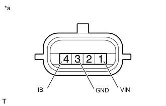
Text in Illustration *a Component without harness connected
(Battery Current Sensor Assembly)
Disconnect the cable from the negative (-) battery terminal.
-
Disconnect the A11 battery current sensor assembly connector.
-
Measure the resistance according to the value(s) in the table below.
Standard Resistance Tester Connection Condition Specified Condition 1 (VIN) - 3 (GND) Always 3 to 10 kΩ 1 (VIN) - 4 (IB) Always Below 0.5 kΩ 3 (GND) - 4 (IB) Always 3 to 10 kΩ -
Reconnect the cable to the negative (-) battery terminal.
NG
REPLACE BATTERY CURRENT SENSOR ASSEMBLY Click here
OK
-
-
CHECK HARNESS AND CONNECTOR (BATTERY CURRENT SENSOR ASSEMBLY - ECM)
-
Disconnect the A33 and A35 ECM connectors.
-
Measure the resistance according to the value(s) in the table below.
Standard Resistance (Check for Open) Tester Connection Condition Specified Condition A33-11 (IB) - A11-4 (IB) Always Below 1 Ω A35-22 (VCP2) - A11-1 (VIN) Always Below 1 Ω A35-30 (EPA2) - A11-3 (GND) Always Below 1 Ω Standard Resistance (Check for Short) Tester Connection Condition Specified Condition A33-11 (IB) or A11-4 (IB) - Body ground Always 10 kΩ or higher A35-22 (VCP2) or A11-1 (VIN) - Body ground Always 10 kΩ or higher A35-30 (EPA2) or A11-3 (GND) - Body ground Always 10 kΩ or higher
OK
REPLACE ECM Click here
NG
REPAIR OR REPLACE HARNESS OR CONNECTOR
-