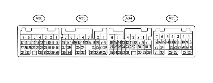
CHARGING SYSTEM TERMINALS OF ECU
-
CHECK ECM
-
Measure the resistance, voltage and waveform according to the value(s) in the table below.
Terminal No.
(Symbol)
Wiring Color Terminal Description Condition Specified Condition A33-2 (BATT) - A34-1 (E03) W - B-R Battery power Always 11 to 14 V A33-11 (IB) - A35-30 (EPA2) R-B - Y-B Battery current sensor Ignition switch ON 0.5 to 4.5 V A33-24 (THB) - A35-30 (EPA2) R-W - Y-B Battery temperature sensor Ignition switch ON 20 to 50°C (68 to 122°F) 1.1 to 2.4 V A34-1 (E03) - Body ground B-R - Body ground Body ground Always Below 1 Ω A35-18 (ALT) - A34-1 (E03) V - B-R Generator Idling with warm engine Pulse generation (See waveform 1) A35-22 (VCP2) - A35-30 (EPA2) G-B - Y-B Power source of battery current sensor assembly Ignition switch ON 4.5 to 5.5 V If the result is not as specified, the ECU may have a malfunction.
-
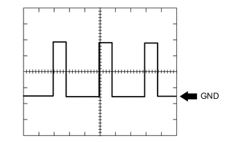
WAVEFORM 1
Generator Tester Connection Tool Setting Vehicle Condition Specified Condition A35-18 (ALT) - A34-1 (E03) 2 V/DIV., 2 msec./DIV. Idling with warm engine Correct waveform as shown in illustration Tech Tips
-
The oscilloscope waveform shown in the illustration is an example for reference only. Noise, chattering, etc. are not shown.
-
A constant value is not output, as the duty ratio varies depending on the electrical load and battery condition.
-
-