LIN COMMUNICATION SYSTEM TERMINALS OF ECU
-
CHECK INSTRUMENT PANEL JUNCTION BLOCK ASSEMBLY AND MAIN BODY ECU (NETWORK GATEWAY ECU)
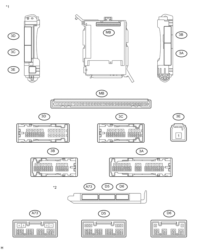
Text in Illustration *1 Instrument Panel Junction Block Assembly *2 Main Body ECU (Network Gateway ECU)
-
Remove the main body ECU (network gateway ECU) from the instrument panel junction block assembly Click here.
-
Measure the voltage and resistance according to the value(s) in the table below.
Terminal No.
(Symbol)
Wiring Color Terminal Description Switch Condition Specified Condition MB-1 (BECU) - Body ground None - Body ground Battery power supply Always 11 to 14 V MB-8 (IG) - Body ground None - Body ground Battery power supply Ignition switch ON 11 to 14 V MB-11 (GND) - Body ground None - Body ground Ground Always Below 1 Ω MB-32 (BMPX) - Body ground None - Body ground Battery power supply Always 11 to 14 V If the result is not as specified, there may be a malfunction in the wire harness.
-
Install the main body ECU (network gateway ECU) onto the instrument panel junction block assembly.
-
Measure the pulses according to the value(s) in the table below.
Terminal No.
(Symbol)
Wiring Color Terminal Description Switch Condition Specified Condition D5-4 (LIN) - D6-1 (GND) LG - B LIN Communication line Ignition switch ON Pulse generation If the result is not as specified, the main body ECU (network gateway ECU) or instrument panel junction block assembly may have a malfunction.
-
-
CHECK POWER WINDOW REGULATOR MASTER SWITCH ASSEMBLY

Text in Illustration *1 for RHD *2 for LHD
-
Disconnect the F6*1 or E8*2 power window regulator master switch assembly connector.
-
Measure the voltage and resistance according to the value(s) in the table below.
Terminal No.
(Symbol)
Wiring Color Terminal Description Condition Specified Condition F6-5 (GND) - Body ground*1 B - Body ground Ground Always Below 1 Ω E8-5 (GND) - Body ground*2 F6-12 (+B) - Body ground*1 SB - Body ground Battery power supply Always 11 to 14 V E8-12 (+B) - Body ground*2 If the result is not as specified, there may be a malfunction in the wire harness.
*1 : for RHD
*2 : for LHD
-
-
CHECK CERTIFICATION ECU (SMART KEY ECU ASSEMBLY) (w/ Entry and Start System)

-
Disconnect the D41 and D48 certification ECU (smart key ECU assembly) connectors.
-
Measure the voltage and resistance according to the value(s) in the table below.
Terminal No.
(Symbol)
Wiring Color Terminal Description Switch Condition Specified Condition D48-2 (+B) - D48-11 (GND) R - B Battery power supply Always 11 to 14 V D48-11 (GND) - Body ground B - Body ground Ground Always Below 1 Ω -
Connect the D41 and D48 certification ECU (smart key ECU assembly) connectors.
-
Measure the voltage according to the value(s) in the table below.
Terminal No.
(Symbol)
Wiring Color Terminal Description Switch Condition Specified Condition D41-5 (IG2) - D48-11 (GND) Y - B Battery power supply Ignition switch ON 11 to 14 V If the result is not as specified, there may be a malfunction in the wire harness.
-
-
CHECK STEERING LOCK ACTUATOR ASSEMBLY (w/ Entry and Start System)

-
Disconnect the D59 steering lock actuator assembly connector.
-
Measure the voltage and resistance according to the value(s) in the table below.
Terminal No.
(Symbol)
Wiring Color Terminal Description Switch Condition Specified Condition D59-1 (GND) - Body ground B - Body ground Ground Always Below 1 Ω D59-6 (IGN1) - D59-1 (GND) BR - B Battery power supply Ignition switch ON 11 to 14 V D59-7 (B) - D59-1 (GND) SB - B Battery power supply Always 11 to 14 V If the result is not as specified, there may be a malfunction in the wire harness.
-
-
CHECK ID CODE BOX (IMMOBILISER CODE ECU) (w/ Entry and Start System with ID Code Box)
-
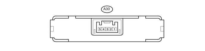
Disconnect the A30 ID code box (immobiliser code ECU) connector.
-
Measure the voltage and resistance according to the value(s) in the table below.
Terminal No.
(Symbol)
Wiring Color Terminal Description Condition Specified Condition A30-1 (+B) - A30-5 (GND) R-W - B-Y Battery power supply Always 11 to 14 V A30-5 (GND) - Body ground B-Y - Body ground Ground Always Below 1 Ω If the result is not as specified, there may be a malfunction in the wire harness.
-