MAIN BODY ECU REMOVAL
CAUTION / NOTICE / HINT
Tech Tips
-
Use the same procedure for RHD and LHD vehicles.
-
The procedure listed below is for LHD vehicles.
PROCEDURE
-
REMOVE INSTRUMENT SIDE PANEL LH
-
REMOVE NO. 1 INSTRUMENT PANEL UNDER COVER SUB-ASSEMBLY (w/o Knee Airbag)
-
REMOVE NO. 1 INSTRUMENT PANEL UNDER COVER SUB-ASSEMBLY (w/ Knee Airbag)
-
REMOVE INSTRUMENT PANEL JUNCTION BLOCK ASSEMBLY
-
Disengage the clamp.
-
Disconnect the connector from the power steering ECU assembly.
-
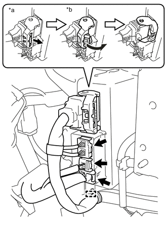
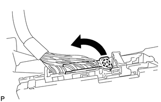
As shown in the illustration, pull out the lock of the lock lever and turn the lock lever to disconnect the connector.
Text in Illustration *a Pull out the lock *b Turn the lock lever
-
-
Disconnect the 3 connectors from the power steering ECU.
-
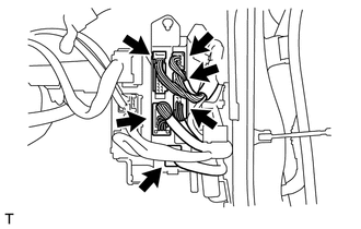
Disconnect the 6 front side connectors from the instrument panel junction block assembly indicated as shown in the illustration.
-
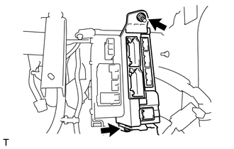
Remove the bolt, nut and the instrument panel junction block assembly.
-
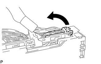
Disconnect the connector indicated as shown in the illustration.
-
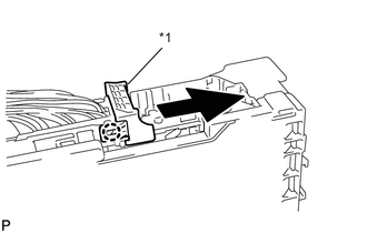
Text in Illustration *1 Lever Disengage the claw and slide the lever upwards.
-
Disconnect the connector indicated as shown in the illustration.
-
Remove the instrument panel junction block assembly.
-
-
REMOVE NETWORK GATEWAY ECU
-
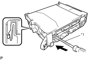
Press the claw on the instrument panel junction block assembly side, as shown in the illustration, to release the lock.
-
With the instrument panel junction block assembly side, insert the screwdriver with its tip wrapped in protective tape between the network gateway ECU and the instrument panel junction block assembly.
Note
Use a blade screwdriver with a diameter of 5.0 to 6.3 mm (0.197 to 0.248 in.), and with a length of 90mm (3.543 in.) or longer.
Text in Illustration *1 Protective Tape -
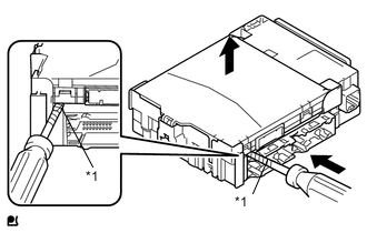
Text in Illustration *1 Protective Tape Using the screwdriver with its tip wrapped with protective tape, carefully raise the network gateway ECU until the connector becomes disengaged.
Note
-
Do not twist the screwdriver to raise the network gateway ECU.
-
If any terminals of the connectors, locking parts or cases are deformed or damaged, replace the instrument panel junction block assembly or the network gateway ECU.
-
-
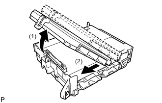
Raise the network gateway ECU as shown by arrow 1, and then pull it out as shown by arrow 2 in the illustration.
Note
Do not touch the network gateway ECU connector terminals.
-