STEERING GEAR REASSEMBLY

PROCEDURE
-
INSTALL STEERING RACK GUIDE
-
Apply grease to the steering rack guide spring and the contact surface of the rack guide.
-
Install the rack guide and the steering rack guide spring.
-
Apply three bond to 2 or 3 threads of the steering rack guide spring cap.
-
Temporarily install the steering rack guide spring cap.
-
-
ADJUST TOTAL PRELOAD
-
INSTALL STEERING RACK END SUB-ASSEMBLY
-
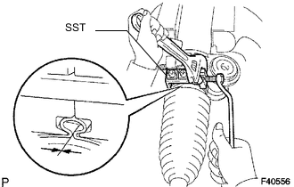
Using SST, install the steering rack end subassembly.
- SST
- 09922-10010
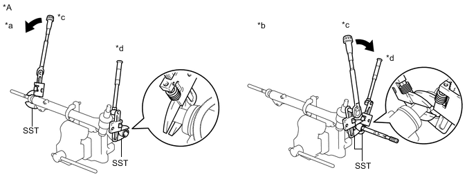
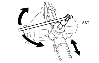
Text in Illustration *A for LHD - - *a LH Side *b RH Side *c Turn *d Hold 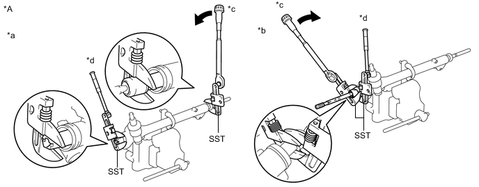
Text in Illustration *A for RHD - - *a LH Side *b RH Side *c Turn *d Hold Tech Tips
Using SST, hold the steering rack and install the steering rack end sub-assembly.
- Torque:
- 103 N*m { 1050 kgf*cm, 76 ft.*lbf }
Note
-
Use the formula to calculate special torque values for situations where SST is combined with a torque wrench Click here.
-
Turn SST in the direction as shown in the illustration.
-
Fix the steering rack firmly in place.
-
-
INSTALL NO. 1 STEERING RACK BOOT
Tech Tips
Use the same procedure for both the LH side and RH side.
-
Wipe the old grease off of the No. 1 steering rack boot and rack end mating groove.
-
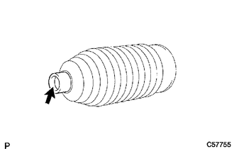
Apply silicone grease to the inside of the small opening of a new No. 1 steering rack boot.
-
Install the No. 1 steering rack boot to the groove on the rack housing.
Note
-
Be careful not to damage or twist the boot.
-
Make sure that the boot is free of rust and foreign matter.
-
-
-
INSTALL NO. 1 STEERING RACK BOOT CLAMP
Tech Tips
Use the same procedure for both the LH side and RH side.
-
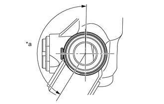
Text in Illustration *a 150° Install the new No. 1 steering rack boot clamp to the No. 1 steering rack boot in such a way that the staked part of the clamp is positioned with in the range, as shown in the illustration.
-
Using SST, tighten a new No. 1 steering rack boot clamp as shown in the illustration.
- SST
- 09521-24010
Clearance 2.0 mm (0.079 in.) or less Note
-
Be careful not to damage the No. 1 steering rack boot.
-
If the No. 1 steering rack boot is fissured, damaged or deteriorated, replace it with a new one.
-
-
INSTALL STEERING RACK BOOT CLIP
Tech Tips
Use the same procedure for both the LH side and RH side.
-
Using pliers, install the steering rack boot clip.
-
-
INSPECT RACK AND PINION POWER STEERING GEAR ASSEMBLY
-
Using SST, rotate the pinion shaft to see if both the left and the right steering rack boots expand and contract smoothly.
- SST
- 09616-00011
Note
Set the pinion shaft at the neutral position after the inspection.
Tech Tips
If the operation cannot be done as specified, use a new steering rack boot clamp and reinstall the steering rack boots.
-
-
INSTALL TIE ROD END SUB-ASSEMBLY LH
-
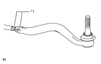
Text in Illustration *1 Matchmark Temporarily tighten the lock nut and tie rod end sub-assembly LH to the steering rack end sub-assembly until the matchmarks are aligned.
Tech Tips
After adjusting the front wheel alignment, securely tighten the lock nut.
- Torque:
- Temporarily tighten
- 5.0 N*m { 51 kgf*cm, 44 in.*lbf }
- Securely tighten
- 85 N*m { 869 kgf*cm, 63 ft.*lbf }
-
-
INSTALL TIE ROD END SUB-ASSEMBLY RH
Tech Tips
Use the procedure as for the LH side.