STEERING GEAR REMOVAL

CAUTION / NOTICE / HINT
Note
-
Be sure to align the front wheels straight ahead when removing and installing the steering gear assembly.
-
When disconnecting the steering intermediate shaft assembly and the pinion shaft of the steering gear assembly, be sure to place matchmarks before servicing.
Tech Tips
-
Use the same procedure for RHD and LHD vehicles.
-
The procedure listed below is for LHD vehicles.
PROCEDURE
-
PLACE FRONT WHEELS FACING STRAIGHT AHEAD
-
REMOVE FRONT WHEELS
-
SECURE STEERING WHEEL ASSEMBLY
-
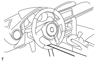
Secure the steering wheel assembly with the seat belt in order to prevent rotation.
Tech Tips
This operation is useful to prevent damage to the spiral cable.
-
-
REMOVE NO. 1 ENGINE UNDER COVER
-
REMOVE NO. 2 ENGINE UNDER COVER
-
DISCONNECT FRONT STABILIZER LINK ASSEMBLY LH
-
Remove the nut and front stabilizer link assembly LH from the front stabilizer bar.
If the ball joint turns together with the nut, use a hexagon wrench to hold the stud bolt.
-
-
DISCONNECT FRONT STABILIZER LINK ASSEMBLY RH
Tech Tips
Use the same procedure as for the LH side.
-
REMOVE FRONT STABILIZER BAR
-
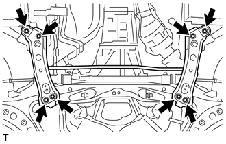
Remove the 8 bolts, and remove the front stabilizer bar together with the rear body mounting cushion sub-assembly LH and RH from the front suspension cross member.
-
-
SEPARATE STEERING INTERMEDIATE SHAFT ASSEMBLY
-
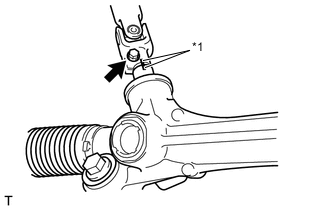
Text in Illustration *1 Matchmark Put matchmarks on the steering intermediate shaft assembly and rack and pinion power steering gear assembly.
-
Remove the bolt.
-
Disconnect the steering intermediate shaft assembly from the rack and pinion power steering gear assembly.
-
-
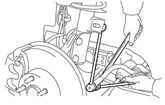
DISCONNECT TIE ROD END SUB-ASSEMBLY LH
-
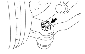
Remove the cotter pin and nut.
-
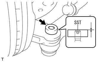
Install SST to the tie rod end sub-assembly LH.
- SST
- 09960-20010 ( 09961-02060 )
Note
Make sure that the lower ends of the tie rod end sub-assembly LH and SST are aligned.
-
Secure SST using a string.
Note
Be sure to tighten the string firmly to secure SST to the steering knuckle to prevent SST from falling off.
-
Using SST, separate the tie rod end sub-assembly LH from the steering knuckle.
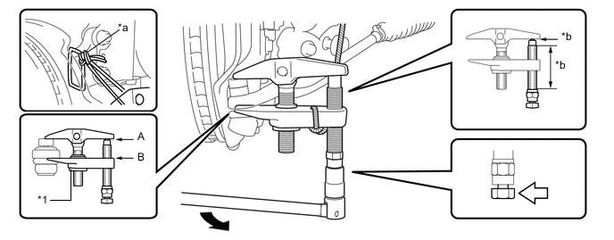
Text in Illustration *1 Center Nut - - *a String *b Grease Application Area 
Place the wrench here. - - - SST
- 09960-20010 ( 09961-02010 )
CAUTION:
Apply grease to the bolt threads and the tip of SST.
Note
-
Install SST with the center nut so that A and B shown in the illustration are parallel. Otherwise, the dust cover may be damaged.
-
Be sure to place the wrench on the part indicated in the illustration.
-
Do not damage the front disc brake dust cover.
-
Do not damage the ball joint dust cover.
-
Do not damage the steering knuckle.
-
-
DISCONNECT TIE ROD END SUB-ASSEMBLY RH
Tech Tips
Use the same procedure as for the LH side.
-
REMOVE RACK AND PINION POWER STEERING GEAR ASSEMBLY
-
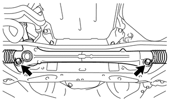
Remove the 2 bolts and rack and pinion power steering gear assembly.
-