STEERING GEAR DISASSEMBLY

PROCEDURE
-
SECURE RACK AND PINION POWER STEERING GEAR ASSEMBLY
-
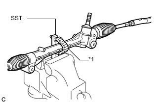
Text in Illustration *1 Protective Tape Using SST, secure the rack and pinion power steering gear assembly in a vise.
- SST
- 09612-00012
Tech Tips
Tape SST before use.
-
-
REMOVE TIE ROD END SUB-ASSEMBLY LH
-
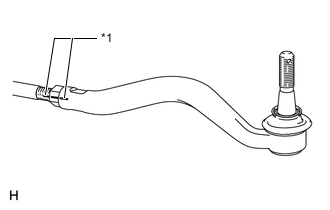
Text in Illustration *1 Matchmark Put matchmarks on the tie rod end sub-assembly LH and the steering rack end sub-assembly.
-
Remove the tie rod end sub-assembly LH and lock nut.
-
-
REMOVE TIE ROD END SUB-ASSEMBLY RH
Tech Tips
Use the same procedure as for the LH side.
-
REMOVE STEERING RACK BOOT CLIP
Tech Tips
Use the same procedure for both the LH side and RH side.
-
Using pliers, remove the steering rack boot clip.
-
-
REMOVE NO. 1 STEERING RACK BOOT CLAMP
Tech Tips
Use the same procedure for both the LH side and RH side.
-
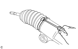
Using a screwdriver, remove the No. 1 steering rack boot clamp.
Note
Be careful not to damage the No. 1 steering rack boot.
-
-
REMOVE NO. 1 STEERING RACK BOOT
Note
If the No. 1 steering rack boot is fissured, damaged or deteriorated, replace it with a new one.
Tech Tips
Use the same procedure for both the LH side and RH side.
-
REMOVE STEERING RACK END SUB-ASSEMBLY
-
Using SST, remove the steering rack end sub-assembly.
- SST
- 09922-10010
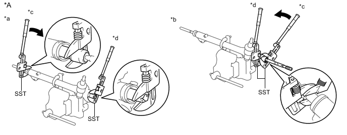
Text in Illustration *A for LHD - - *a LH Side *b RH Side *c Turn *d Hold Note
Turn SST in the direction as shown in the illustration.
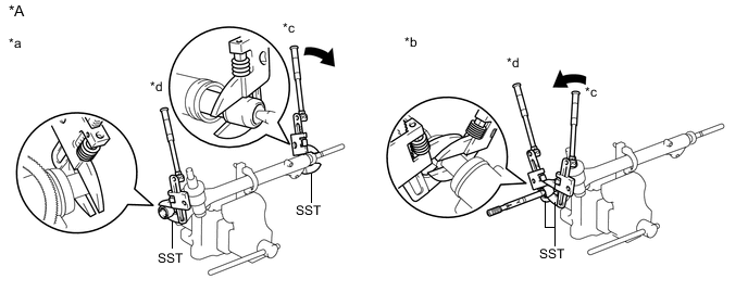
Text in Illustration *A for RHD - - *a LH Side *b RH Side *c Turn *d Hold Note
Turn SST in the direction as shown in the illustration.
-
-
REMOVE STEERING RACK GUIDE
-
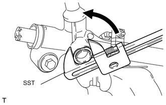
Using SST, remove the lock nut.
- SST
- 09922-10010
Note
Turn SST in the direction as shown in the illustration.
-
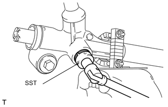
Using SST, remove the steering rack guide spring cap.
- SST
- 09631-10021
-
Remove the steering rack guide and the steering rack guide spring.
-