STEERING PAD SWITCH INSPECTION
PROCEDURE
-
INSPECT STEERING PAD SWITCH ASSEMBLY
-
Measure the resistance according to the value(s) in the table below.
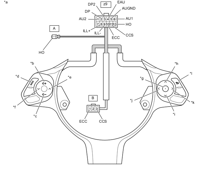
Text in Illustration *a Component without harness connected
(Steering Pad Switch Assembly)
*b VOL+ *c VOL- *d MODE *e SEEK+ *f SEEK- *g ENTER *h UP *i DOWN *j LEFT *k RIGHT *l BACK Standard Resistance Tester Connection Condition Specified Condition z9-6 (AU1) - z9-5 (AU-GND) No switch pushed 98 to 102 kΩ VOL+ switch pushed Below 2.5 Ω VOL- switch pushed 322 to 336 Ω SEEK+ switch pushed 980 to 1020 Ω SEEK- switch pushed 3048 to 3172 Ω z9-2 (DP) - z9-4 (EAU) No switch pushed 98 to 102 kΩ LEFT switch pushed Below 2.5 Ω UP switch pushed 322 to 336 Ω DOWN switch pushed 980 to 1020 Ω RIGHT switch pushed 3048 to 3172 Ω z9-1 (AU2) - z9-5 (AUGND) No switch pushed 98 to 102 kΩ MODE switch pushed Below 2.5 Ω z9-3 (DP2) - z9-4 (EAU) No switch pushed 98 to 102 kΩ ENTER switch pushed Below 2.5 Ω BACK switch pushed 980 to 1020 Ω z9-12 (HO) - A-1 (HO) Always Below 2.5 Ω z9-10 (ECC) - B-1 (ECC)* Always Below 2.5 Ω z9-11 (ECC) - B-3 (ECC)* Always Below 2.5 Ω *: w/ Cruise Control System
If the result is not as specified, replace the steering pad switch assembly.
-
Check the illumination.
-
Connect a positive (+) lead from the battery to the terminal z9-8 (ILL+) and a negative (-) lead to the terminal z9-9 (ILL-) of the steering pad switch assembly connector.
-
Check that the switch illumination illuminates.
OK The steering pad switch illumination illuminates. If the result is not as specified, replace the steering pad switch assembly.
-
-