STEERING COLUMN ASSEMBLY INSTALLATION
CAUTION / NOTICE / HINT
Tech Tips
-
Use the same procedure for RHD and LHD vehicles.
-
The procedure listed below is for LHD vehicles.
PROCEDURE
-
INSPECT STEERING COLUMN ASSEMBLY
-
INSTALL STEERING COLUMN ASSEMBLY
-
Install the steering column assembly with the 2 nuts and new bolt.
- Torque:
- 40 N*m { 408 kgf*cm, 30 ft.*lbf }
Note
When installing the steering column assembly, be careful that the wire harness does not interfere with or is not pinched between other parts.
-
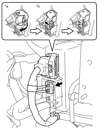
Text in Illustration *a Return the lock lever *b Push in the lock Engage the clamp.
-
Connect the 2 connectors to the power steering ECU.
-
As shown in the illustration, return the lock lever to its original position to connect the connector and securely push in the lock of the lock lever.
-
-
Connect the each connector and engage the wire harness clamps to the steering column assembly.
-
-
INSTALL STEERING INTERMEDIATE SHAFT ASSEMBLY
-
Pass the steering intermediate shaft assembly through the hole in the body from the inside of the cabin.
-
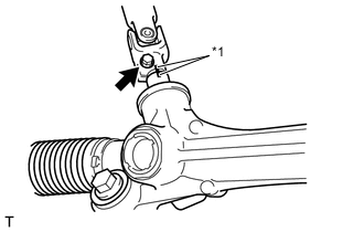
Text in Illustration *1 Matchmark Connect the steering intermediate shaft assembly to the rack and pinion power steering gear assembly.
Note
Align the matchmarks on the steering intermediate shaft assembly and the rack and pinion power steering gear assembly.
-
Install the new bolt.
- Torque:
- 35 N*m { 357 kgf*cm, 26 ft.*lbf }
-
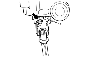
Text in Illustration *1 Matchmark Install the steering intermediate shaft assembly to the steering column assembly.
Note
Align the matchmarks on the steering intermediate shaft assembly and the steering column assembly.
-
Install the new bolt.
- Torque:
- 35 N*m { 357 kgf*cm, 26 ft.*lbf }
-
Engage the 4 claws and install the dust seal.
-
-
INSTALL TURN SIGNAL SWITCH ASSEMBLY WITH SPIRAL CABLE SUB-ASSEMBLY
Note
-
Do not replace the spiral cable with the battery connected and the ignition switch ON.
-
Do not rotate the spiral cable without the steering wheel with the battery connected and the ignition switch ON.
-
Ensure that the steering wheel is installed and aligned straight when inspecting the steering sensor.
-
With the clamp loosened, install the turn signal switch assembly with spiral cable sub-assembly to the steering column assembly.
-
Engage the claw on the turn signal switch assembly with spiral cable sub-assembly to the steering column assembly and tighten the clamp.
-
Connect the each connector to the turn signal switch assembly with spiral cable sub-assembly.
-
-
INSTALL UPPER STEERING COLUMN COVER
-
Engage the 2 claws to install the upper steering column cover.
-
-
INSTALL LOWER STEERING COLUMN COVER
-
w/ Knee Airbag
-
Engage the 4 claws to install the lower steering column cover.
-
Install the 2 screws.
-
-
w/o Knee Airbag
-
Engage the 6 claws to install the lower steering column cover.
-
Install the 2 screws.
-
-
-
INSTALL STEERING COLUMN COVER SUPPORT (w/ Entry and Start System)
-
Engage the 4 claws and install the steering column cover support.
-
-
INSTALL UPPER INSTRUMENT PANEL METER ORNAMENT
-
INSTALL METER HOOD SUB-ASSEMBLY
-
INSTALL INSTRUMENT PANEL ORNAMENT (w/ Large Ornament Panel)
-
INSTALL CENTER INSTRUMENT CLUSTER FINISH PANEL SUB-ASSEMBLY (w/o Large Ornament Panel)
-
TURN FRONT WHEELS TO FACE STRAIGHT AHEAD
-
INSPECT AND ADJUST SPIRAL CABLE WITH SENSOR SUB-ASSEMBLY
-
INSPECT STEERING WHEEL CENTER POINT
-
INSTALL STEERING WHEEL ASSEMBLY
-
INSTALL LOWER NO. 1 INSTRUMENT PANEL AIRBAG ASSEMBLY (w/ Knee Airbag)
-
INSTALL NO. 1 INSTRUMENT PANEL UNDER COVER SUB-ASSEMBLY (w/o Knee Airbag)
-
INSTALL INSTRUMENT SIDE PANEL (w/o Knee Airbag)
-
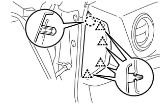
Engage the 4 clips and claw to install the instrument side panel.
-
-
INSTALL NO. 1 ENGINE UNDER COVER
-
INSTALL NO. 2 ENGINE UNDER COVER
-
VSC SENSOR NEUTRAL MEMORIZATION
-
ROTATION ANGLE SENSOR INITIALIZATION AND TORQUE SENSOR ZERO POINT CALIBRATION