STEERING COLUMN ASSEMBLY DISASSEMBLY
CAUTION / NOTICE / HINT
Note
-
When using a vise, do not overtighten it.
-
Do not drop the steering column assembly, strike it with tools or subject it to impacts.
-
If the steering column assembly is subjected to an impact, replace it with a new one.
-
Do not pull the wire harness of the steering column assembly.
-
Do not allow any moisture to come into contact with the steering column assembly.
-
Do not loosen any bolts not mentioned in the procedure.
PROCEDURE
-
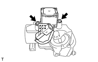
REMOVE STEERING COLUMN UPPER WITH SWITCH BRACKET ASSEMBLY (w/o Entry and Start System)
-
Using a center punch, mark the center of the 2 tapered-head bolts.
-
Using a 3 to 4 mm (0.118 to 0.157 in.) diameter drill bit, drill a hole in each tapered-head bolt.
-
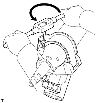
Using a screw extractor, remove each tapered-head bolt, and then remove the steering column upper with switch bracket assembly from the steering column assembly.
-
-
REMOVE STEERING LOCK ACTUATOR ASSEMBLY (w/ Entry and Start System)
-
Using a center punch, mark the center of the 2 tapered-head bolts.
-
Using a 3 to 4 mm (0.118 to 0.157 in.) diameter drill bit, drill a hole in each tapered-head bolt.
-
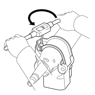
Using a screw extractor, remove each tapered-head bolt, and then remove the steering lock actuator assembly from the steering column assembly.
-
-
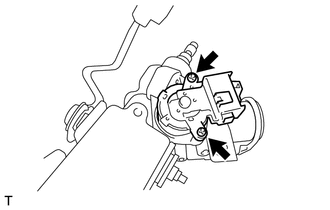
REMOVE TRANSPONDER KEY AMPLIFIER (w/o Entry and Start System)
-
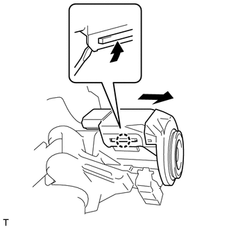
Slide the transponder key amplifier, disengage the 2 claws and then remove the transponder key amplifier as shown in the illustration.
-
-
REMOVE UN-LOCK WARNING SWITCH ASSEMBLY (w/o Entry and Start System)
-
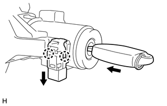
Insert the key.
-
Disengage the 2 claws and slide the un-lock warning switch assembly to remove it as shown in the illustration.
-
-
REMOVE KEY INTERLOCK SOLENOID (for Automatic Transmission without Entry and Start System)
-
Remove the 2 screws and the key interlock solenoid from the steering column upper bracket assembly.
-
Disengage the clamp.
-
-
REMOVE IGNITION SWITCH LOCK CYLINDER ASSEMBLY (w/o Entry and Start System)
-
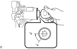
Text in Illustration *a LOCK *b ACC Turn the ignition switch lock cylinder assembly to the ACC position.
-
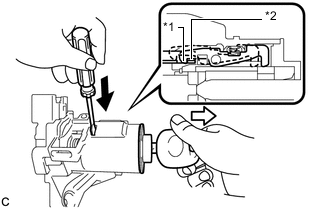
Text in Illustration *1 Claw *2 Stopper 
Push 
Pull Insert a screwdriver into the hole of the steering column upper bracket assembly as shown in the illustration. Pull the ignition switch lock cylinder assembly until its claw contacts the stopper of the steering column upper bracket assembly.
Note
Make sure to pull the ignition switch lock cylinder assembly until its claw contacts the stopper of the steering column upper bracket assembly. Failure to do so will affect later work operations.
-
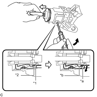
Text in Illustration *1 Claw *2 Stopper *a Claw disengaged *b Driver Insertion Hole Tilt Pull out Insert a screwdriver into the hole of the steering column upper bracket assembly. Tilt the screwdriver as shown in the illustration to disengage the claw of the ignition switch lock cylinder assembly, and pull out the ignition switch lock cylinder assembly from the steering column upper bracket assembly.
-
-
REMOVE IGNITION OR STARTER SWITCH ASSEMBLY (w/o Entry and Start System)
-
Remove the 2 screws and the ignition or starter switch assembly from the steering column upper bracket assembly.
-