STEERING COLUMN ASSEMBLY REMOVAL
CAUTION / NOTICE / HINT
CAUTION:
Some of these service operations affect the SRS airbag system. Read the precautionary notices concerning the SRS airbag system before servicing the steering column. Click here
Tech Tips
-
Use the same procedure for RHD and LHD vehicles.
-
The procedure listed below is for LHD vehicles.
PROCEDURE
-
PRECAUTION
-
TURN FRONT WHEELS TO FACE STRAIGHT AHEAD
-
REMOVE NO. 1 ENGINE UNDER COVER
-
REMOVE NO. 2 ENGINE UNDER COVER
-
REMOVE STEERING WHEEL ASSEMBLY
-
REMOVE INSTRUMENT SIDE PANEL (w/o Knee Airbag)
-
Text in Illustration *1 Moulding Remover Using a moulding remover, disengage the claw and 4 clips and remove the instrument side panel.
-
-
REMOVE NO. 1 INSTRUMENT PANEL UNDER COVER SUB-ASSEMBLY (w/o Knee Airbag)
-
REMOVE LOWER NO. 1 INSTRUMENT PANEL AIRBAG ASSEMBLY (w/ Knee Airbag)
-
REMOVE CENTER INSTRUMENT CLUSTER FINISH PANEL SUB-ASSEMBLY
-
REMOVE METER HOOD SUB-ASSEMBLY
-
REMOVE UPPER INSTRUMENT PANEL METER ORNAMENT
-
REMOVE STEERING COLUMN COVER SUPPORT (w/ Entry and Start System)
-
Disengage the 4 claws and remove the steering column cover support.
-
-
REMOVE LOWER STEERING COLUMN COVER
-
w/ Knee Airbag
-
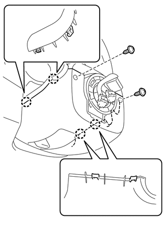
Remove the 2 screws.
-
Disengage the 4 claws and remove the lower steering column cover.
-
-
w/o Knee Airbag
-
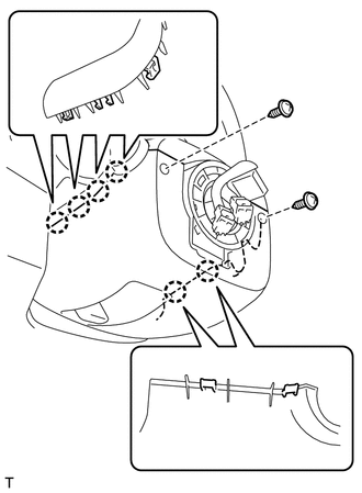
Remove the 2 screws.
-
Disengage the 6 claws and remove the lower steering column cover.
-
-
-
REMOVE UPPER STEERING COLUMN COVER
-
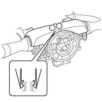
Disengage the 2 claws to remove the upper steering column cover.
-
-
REMOVE TURN SIGNAL SWITCH ASSEMBLY WITH SPIRAL CABLE SUB-ASSEMBLY
-
Disconnect the each connector from the turn signal switch assembly with spiral cable sub-assembly.
-
Using pliers, loosen the clamp.
-
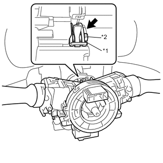
Text in Illustration *1 Clamp *2 Claw With the clamp loosened, use a screwdriver to disengage the claw, and remove the turn signal switch assembly with spiral cable sub-assembly from the steering column assembly.
Note
-
Do not replace the spiral cable with the battery connected and the ignition switch ON.
-
Do not rotate the spiral cable with the battery connected and the ignition switch ON.
-
Ensure that the steering wheel is installed and aligned straight when inspecting the steering sensor.
-
-
-
REMOVE STEERING INTERMEDIATE SHAFT ASSEMBLY
-
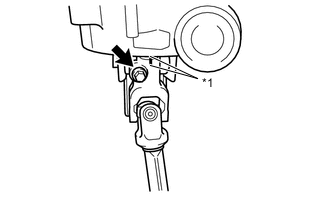
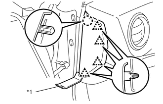
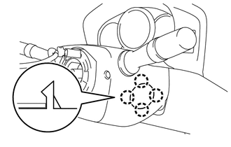
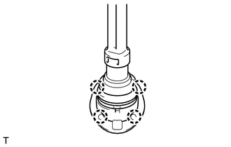
Text in Illustration *1 Matchmark Put matchmarks on the steering intermediate shaft assembly and the steering column assembly.
-
Remove the bolt and separate the steering intermediate shaft assembly from the steering column assembly.
-
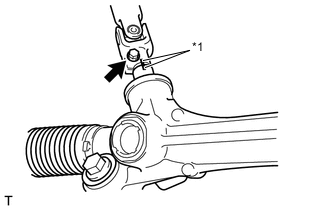
Text in Illustration *1 Matchmark Put matchmarks on the steering intermediate shaft assembly and the rack and pinion power steering gear assembly.
-
Remove the bolt and separate the steering intermediate shaft assembly from the rack and pinion power steering gear assembly.
-
Disengage the 4 claws remove the steering intermediate shaft assembly from the exterior of the vehicle cabin.
-
-
REMOVE STEERING COLUMN ASSEMBLY
-
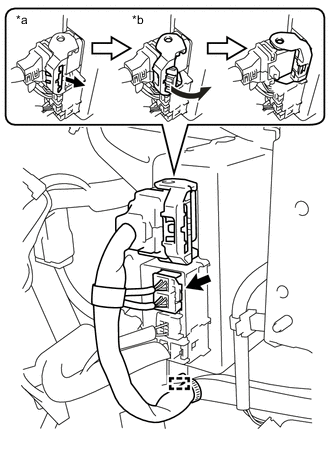
Text in Illustration *a Pull out the lock *b Turn the lock lever Disconnect the 2 connectors from the power steering ECU assembly.
-
As shown illustration, pull out the lock of the lock lever and turn the lock lever to disconnect the connector.
-
-
Disengage the clamp.
-
Disconnect the each connector and disengage the wire harness clamps from the steering column assembly.
-
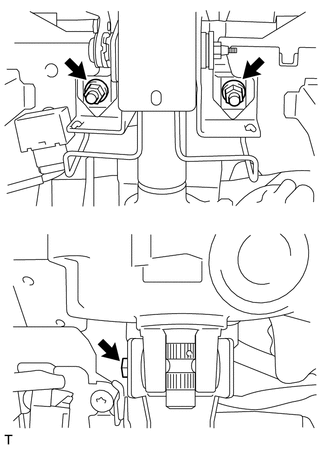
Remove the bolt and 2 nuts to remove the steering column assembly.
Tech Tips
When pulling the bolts out, lifting the motor section of the steering column assembly and tilting the steering column assembly will make it easier to remove the bolts.
-