BRAKE BOOSTER(for LHD) INSTALLATION
PROCEDURE
-
INSTALL BRAKE MASTER CYLINDER PUSH ROD CLEVIS
-
Temporarily install the lock nut and brake master cylinder push rod clevis to the brake booster assembly.
-
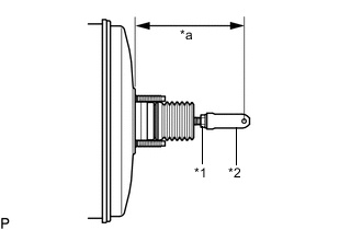
Text in Illustration *1 Lock Nut *2 Brake Master Cylinder Push Rod Clevis *a Push Rod Length Set the push rod length as shown in the illustration.
Push rod length 155.2 mm (6.11 in.) -
Tighten the lock nut.
- Torque:
- 19 N*m { 194 kgf*cm, 14 ft.*lbf }
-
-
INSTALL BRAKE BOOSTER ASSEMBLY
-
Install the 4 nuts to the brake booster assembly.
- Torque:
- 18 N*m { 184 kgf*cm, 13 ft.*lbf }
-
-
INSTALL FRONT NO. 2 BRAKE TUBE
-
Connect 2 clips and install the front No. 2 brake tube.
-
Using a union nut wrench 12 mm, connect the front No. 2 brake tube from the brake actuator.
- Torque:
- 19 N*m { 194 kgf*cm, 14 ft.*lbf }
Note
-
Do not bend or damage the brake lines.
-
Do not allow brake lines to twist and interfere with other parts or vehicle body during tightening.
-
Do not allow any foreign matter such as dirt or dust to enter the brake lines.
-
Use the formula to calculate special torque values for situations where the union nut wrench is combined with a torque wrench Click here.
-
-
INSTALL FRONT NO. 1 BRAKE TUBE
-
Connect 2 clips and install the front No. 1 brake tube.
-
Using a union nut wrench 12 mm, connect the front No. 1 brake tube from the brake actuator.
Note
-
Do not bend or damage the brake lines.
-
Do not allow brake lines to twist and interfere with other parts or vehicle body during tightening.
-
Do not allow any foreign matter such as dirt or dust to enter the brake lines.
-
Use the formula to calculate special torque values for situations where the union nut wrench is combined with a torque wrench Click here.
-
-
-
CONNECT VACUUM TUBE CONNECTOR HOSE
-
INSTALL PUSH ROD PIN
-
INSTALL BRAKE MASTER CYLINDER SUB-ASSEMBLY
-
CHECK AND ADJUST BRAKE PEDAL (for Automatic Transmission)
-
CHECK AND ADJUST BRAKE PEDAL (for Manual Transmission)
-
INSTALL TCM (for Automatic Transmission)
-
INSTALL LOWER NO. 1 INSTRUMENT FANEL AIRBAG ASSEMBLY (w/ Knee Airbag)
-
INSTALL NO. 1 INSTRUMENT PANEL UNDER COVER SUB-ASSEMBLY (w/o Knee Airbag)
-
INSTALL INSTRUMENT SIDE PANEL LH (w/o Knee Airbag)
Tech Tips
Use the same procedure for the LH side as for the RH side Click here.