BRAKE PEDAL(except LHD M/T) INSTALLATION
PROCEDURE
-
INSTALL BRAKE PEDAL SUPPORT ASSEMBLY
-
Install the brake pedal support assembly with the 4 nuts.
- Torque:
- 18 N*m { 184 kgf*cm, 13 ft.*lbf }
-
Install the brake pedal support assembly with the 2 bolts.
- Torque:
- 18 N*m { 184 kgf*cm, 13 ft.*lbf }
-
-
INSTALL PUSH ROD PIN
-
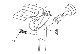
Text in Illustration *1 Push Rod Pin 
Lithium Soap Base Glycol Grease Apply lithium soap base glycol grease to the push rod pin.
-
Connect the brake master cylinder push rod clevis to the brake pedal support assembly with the push rod pin, and install a new clip as shown in the illustration.
Note
After installation, check that the pedal operates smoothly.
-
-
INSTALL STOP LIGHT SWITCH MOUNTING ADJUSTER
-
Engage the 2 claws and install the stop light switch mounting adjuster.
-
-
INSPECT AND ADJUST BRAKE PEDAL
-
INSPECT AND ADJUST BRAKE PEDAL HEIGHT
-
INSPECT BRAKE PEDAL FREE PLAY
-
INSPECT BRAKE PEDAL RESERVE DISTANCE
-
INSTALL STOP LIGHT SWITCH ASSEMBLY
-
INSTALL TCM (for Automatic Transmission)
-
INSTALL LOWER NO. 1 INSTRUMENT PANEL AIRBAG ASSEMBLY (w/ Knee Airbag)
-
INSTALL NO. 1 INSTRUMENT PANEL UNDER COVER SUB-ASSEMBLY (w/o Knee Airbag)
-
INSTALL INSTRUMENT SIDE PANEL LH (w/o Knee Airbag)
Tech Tips
Use the same procedure for the LH side as for the RH side Click here