BRAKE ACTUATOR INSTALLATION
PROCEDURE
-
INSTALL BRAKE ACTUATOR ASSEMBLY WITH BRAKE ACTUATOR BRACKET
-
Install the brake actuator assembly with brake actuator bracket using the 4 bolts.
- Torque:
- 33 N*m { 338 kgf*cm, 24 ft.*lbf }
-
Connect the brake actuator connector to the brake actuator.
-
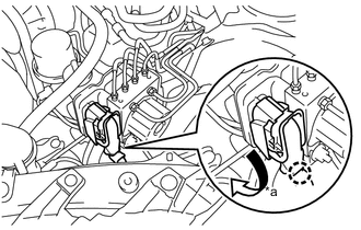
Text in Illustration *a Turn Turn the locking lever downwards, and engage the wire harness connector locking claw to lock the connector.
Note
-
Make sure that the actuator connector can be connected smoothly. Do not allow water, oil or dirt to enter.
-
Make sure that the connector is locked securely.
-
-
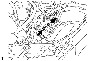
Using a union nut wrench 12 mm, tighten 2 brake tubes.
- Torque:
- 19 N*m { 194 kgf*cm, 14 ft.*lbf }
Note
Use the formula to calculate the special torque values for situations where the union nut wrench is combined with a torque wrench Click here.
-
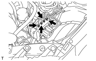
Using a union nut wrench 10 mm, tighten the 4 brake tubes.
- Torque:
- 15 N*m { 155 kgf*cm, 11 ft.*lbf }
Note
Use the formula to calculate the special torque values for situations where the union nut wrench is combined with a torque wrench Click here.
-
Connect the front speed sensor LH harness clamp to the brake actuator bracket assembly.
-
Connect the cooler pipe to the clamp.
-
Connect the 2 harness clamp to the brake actuator bracket.
-
-
ADD BRAKE FLUID
-
BLEED BRAKE SYSTEM
-
INSPECT FLUID LEAK
-
INSPECT BRAKE FLUID LEVEL
-
INSTALL FRONT FENDER LINER LH
-
INSTALL FRONT WHEEL LH
- Torque:
- 120 N*m { 1224 kgf*cm, 89 ft.*lbf }
-
VSC SENSOR NEUTRAL MEMORIZATION
-
INSPECT SPEED SENSOR