REAR SUSPENSION MEMBER REMOVAL
PROCEDURE
-
REMOVE REAR WHEELS
-
REMOVE REAR HEIGHT CONTROL SENSOR SUB-ASSEMBLY LH (w/ HID Headlight System)
-
REMOVE PROPELLER WITH CENTER BEARING SHAFT ASSEMBLY
-
REMOVE EXHAUST TAIL PIPE ASSEMBLY
-
REMOVE REAR DIFFERENTIAL CARRIER ASSEMBLY
-
REMOVE REAR DRIVE SHAFT ASSEMBLY LH
-
REMOVE REAR DRIVE SHAFT ASSEMBLY RH
Tech Tips
Use the same procedure described for the LH side.
-
REMOVE REAR AXLE CARRIER SUB-ASSEMBLY LH
-
REMOVE REAR AXLE CARRIER SUB-ASSEMBLY RH
Tech Tips
Use the same procedure described for the LH side.
-
REMOVE NO. 3 FUEL TANK PROTECTOR (for Metal Type)
-
REMOVE NO. 1 FUEL TANK PROTECTOR (for Clamp Type)
-
REMOVE NO. 2 FUEL TANK PROTECTOR (for Clamp Type)
-
SEPARATE NO. 3 PARKING BRAKE CABLE ASSEMBLY
-
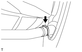
Remove the clamp and separate the No. 3 parking brake cable assembly.
-
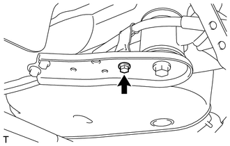
Remove the bolt and separate the No. 3 parking brake cable assembly from rear suspension member lower stopper LH.
-
-
SEPARATE NO. 2 PARKING BRAKE CABLE ASSEMBLY
Tech Tips
Use the same procedure described for the LH side.
-
REMOVE PARKING BRAKE CABLE SUPPORT BRACKET (for LH Side)
-
REMOVE PARKING BRAKE CABLE SUPPORT BRACKET (for RH Side)
Tech Tips
Use the same procedure described for the LH side.
-
REMOVE REAR STABILIZER BAR
-
REMOVE REAR NO. 1 SUSPENSION ARM ASSEMBLY LH
-
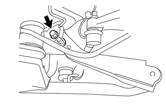
Remove the bolt, nut and rear No. 1 suspension arm assembly LH.
-
-
REMOVE REAR NO. 1 SUSPENSION ARM ASSEMBLY RH
Tech Tips
Use the same procedure described for the LH side.
-
SEPARATE REAR SHOCK ABSORBER WITH COIL SPRING LH
-
SEPARATE REAR SHOCK ABSORBER WITH COIL SPRING RH
Tech Tips
Use the same procedure described for the LH side.
-
SEPARATE REAR NO. 2 SUSPENSION ARM ASSEMBLY LH
-
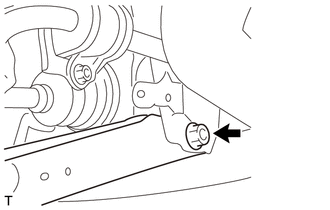
Remove the bolt, nut and rear No. 2 suspension arm assembly LH from the rear suspension member sub-assembly.
-
-
SEPARATE REAR NO. 2 SUSPENSION ARM ASSEMBLY RH
Tech Tips
Use the same procedure described for the LH side.
-
REMOVE TOE CONTROL LINK SUB-ASSEMBLY LH
-
Put matchmarks on the rear No. 2 suspension toe adjust plate and rear suspension member.
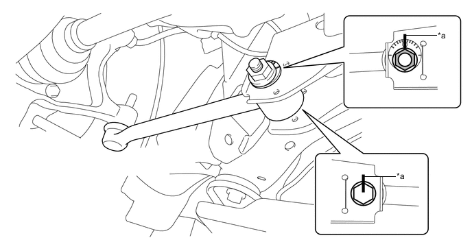
Text in Illustration *a Matchmark - - -
Remove the nut, rear suspension toe adjust cam, rear No. 2 suspension toe adjust plate and toe control link sub-assembly LH.
-
-
REMOVE TOE CONTROL LINK SUB-ASSEMBLY RH
Tech Tips
Use the same procedure described for the LH side.
-
REMOVE REAR SUSPENSION MEMBER SUB-ASSEMBLY
-
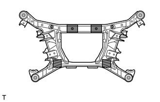
Support the rear suspension member sub-assembly with an engine lifter using 4 attachments or equivalent tools as shown in the illustration.
Text in Illustration 
Attachment Placement Location Note
-
Make sure to secure the rear suspension member sub-assembly to prevent it from dropping.
-
Use the attachments to keep the rear suspension member sub-assembly level.
-
-
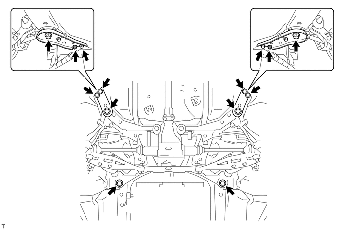
Remove the 8 bolts, 2 rear lower suspension member stoppers, 2 differential support member stoppers and 2 rear suspension member lower stoppers from the rear suspension member.
-
Slowly lower the rear suspension member sub-assembly.
Note
When lowering the rear suspension member sub-assembly, be careful not to damage the vehicle body or other components installed on the vehicle.
-
-
REMOVE REAR UPPER CONTROL ARM ASSEMBLY LH
-
REMOVE REAR UPPER CONTROL ARM ASSEMBLY RH
Tech Tips
Use the same procedure described for the LH side.
-
REMOVE REAR NO. 1 DIFFERENTIAL MOUNT CUSHION
-
REMOVE REAR NO. 2 DIFFERENTIAL MOUNT CUSHION