FRONT SUSPENSION MEMBER INSTALLATION
PROCEDURE
-
INSTALL FRONT CROSS MEMBER SUB-ASSEMBLY
-
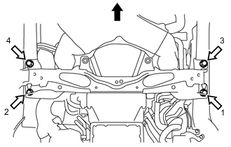
Tighten 4 new bolts in the order shown in the illustration, and temporarily install the front cross member sub-assembly.
Text in Illustration 
Vehicle of Front Side 
Bolt -
Tighten the 4 bolts.
- Torque:
- 95 N*m { 969 kgf*cm, 70 ft.*lbf }
-
-
ADJUST SHIFT LEVER POSITION (for Automatic Transmission)
Note
If the front cross member sub-assembly mounting bolts are loosened even if only slightly, check adjustment with the shift lever Click here.
-
INSTALL RACK AND PINION POWER STEERING GEAR ASSEMBLY
-
INSTALL REAR BODY MOUNTING CUSHION SUB-ASSEMBLY LH
-
INSTALL REAR BODY MOUNTING CUSHION SUB-ASSEMBLY RH
Tech Tips
Perform the same procedure as for the LH side.
-
INSTALL FRONT STABILIZER LINK ASSEMBLY LH
-
INSTALL FRONT STABILIZER LINK ASSEMBLY RH
Tech Tips
Perform the same procedure as for the LH side.
-
INSTALL FRONT LOWER SUSPENSION ARM ASSEMBLY LH
-
INSTALL FRONT LOWER SUSPENSION ARM ASSEMBLY RH
Tech Tips
Perform the same procedure as for the LH side.
-
INSTALL ENGINE ASSEMBLY
-
INSPECT STEERING WHEEL CENTER POINT
-
INSPECT AND ADJUST FRONT WHEEL ALIGNMENT
-
VSC SENSOR NEUTRAL MEMORIZATION
-
HEIGHT CONTROL SENSOR SIGNAL INITIALIZE (w/ HID Headlight System)
-
ADJUST HEADLIGHT AIMING (w/ HID Headlight System)