FRONT STABILIZER BAR INSTALLATION
PROCEDURE
-
INSTALL FRONT NO. 1 STABILIZER BAR BUSHING (for LH Side)
-
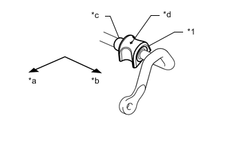
Text in Illustration *1 Front No. 1 Stabilizer Bar Bushing *a Front of the Vehicle *b Outside of the Vehicle *c Stopper Ring *d Arrow Install the front No. 1 stabilizer bar bushing so that it is positioned closer to the outside of the vehicle than the front stabilizer bar stopper ring.
Note
Install the front No. 1 stabilizer bar bushing so that the arrow mark is facing towards the front of the vehicle.
-
-
INSTALL FRONT NO. 1 STABILIZER BAR BUSHING (for RH Side)
Tech Tips
Perform the same procedure as for the LH side.
-
INSTALL FRONT NO. 2 STABILIZER BRACKET LH
-
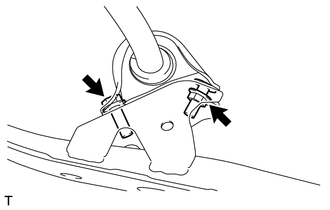
Install the front No. 2 stabilizer bracket LH to the rear body mounting cushion sub-assembly with the bolt and nut.
- Torque:
- Bolt
- 75 N*m { 765 kgf*cm, 55 ft.*lbf }
- Nut
- 25 N*m { 255 kgf*cm, 18 ft.*lbf }
-
-
INSTALL FRONT NO. 2 STABILIZER BRACKET RH
Tech Tips
Perform the same procedure as for the LH side.
-
INSTALL REAR BODY MOUNTING CUSHION SUB-ASSEMBLY LH
-
Install the rear body mounting cushion sub-assembly LH and front stabilizer bar with the 4 new bolts.
- Torque:
- 60 N*m { 612 kgf*cm, 44 ft.*lbf }
-
-
INSTALL REAR BODY MOUNTING CUSHION SUB-ASSEMBLY RH
Tech Tips
Perform the same procedure as for the LH side.
-
INSTALL FRONT STABILIZER LINK ASSEMBLY LH
-
Using a hexagon wrench 6 mm, fix the stud bolt, and install the front stabilizer link assembly LH to the front stabilizer bar with a new nut.
- Torque:
- 46 N*m { 469 kgf*cm, 34 ft.*lbf }
-
Using a hexagon wrench 6 mm, fix the stud bolt, and install the front stabilizer link assembly LH to the front shock absorber with coil spring with a new nut.
- Torque:
- 46 N*m { 469 kgf*cm, 34 ft.*lbf }
-
-
INSTALL FRONT STABILIZER LINK ASSEMBLY RH
Tech Tips
Perform the same procedure as for the LH side.
-
INSTALL REAR ENGINE UNDER COVER LH
-
INSTALL REAR ENGINE UNDER COVER RH
Tech Tips
Perform the same procedure as for the LH side.
-
INSTALL NO. 2 ENGINE UNDER COVER
-
INSTALL NO. 1 ENGINE UNDER COVER
-
INSTALL FRONT WHEEL
- Torque:
- 120 N*m { 1224 kgf*cm, 89 ft.*lbf }
-
STABILIZE SUSPENSION
-
INSPECT STEERING WHEEL CENTER POINT
-
INSPECT AND ADJUST FRONT WHEEL ALIGNMENT
-
VSC SENSOR NEUTRAL MEMORIZATION
-
HEIGHT CONTROL SENSOR SIGNAL INITIALIZE (w/ HID Headlight System)
-
ADJUST HEADLIGHT AIMING (w/ HID Headlight System)