FRONT WHEEL ALIGNMENT ADJUSTMENT
CAUTION / NOTICE / HINT
Note
If the wheel alignment has been adjusted, and if suspension or underbody components have been removed/installed or replaced, be sure to perform the following initialization procedure in order for the system to function normally:
Perform zero point calibration of the yaw rate and acceleration sensor and test mode inspection Click here.
PROCEDURE
-
INSPECT TIRES
-
MEASURE VEHICLE HEIGHT
-
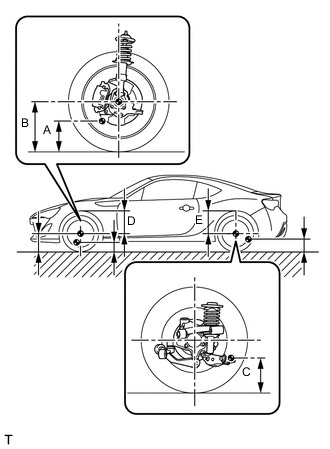
Bounce the vehicle up and down at the corners to stabilize the suspension before inspecting the vehicle height.
Vehicle Height (Unloaded Vehicle) Tire Size Front B - A Rear C Front D Rear E 205/55 R16 146 mm
(5.75 in.)
225 mm
(8.86 in.)
375 mm
(14.76 in.)
372 mm
(14.65 in.)
215/45 R17 146 mm
(5.75 in.)
225 mm
(8.86 in.)
375 mm
(14.76 in.)
372 mm
(14.65 in.)
Note
-
Perform the inspection while the vehicle is empty (with a spare tire, jack and tools on board, and with the fuel tank filled with fuel).
-
The standard value shown here is a value that is used for adjusting the wheel alignment and does not indicate the height of an actual vehicle.
Measuring points A Ground clearance of front lower suspension arm set front bolt center B Ground clearance of front wheel center C Ground clearance of lower control arm set bolt center D Front wheel arch height of front wheel center E Rear wheel arch height of rear wheel center -
-
-
INSPECT CAMBER, CASTER AND STEERING AXIS INCLINATION
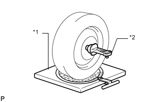
Text in Illustration *1 Alignment tester *2 Camber-Caster-Steering Axis Inclination Gauge Note
Perform the inspection while the vehicle is empty (with a spare tire, jack and tools on board, and with the fuel tank filled with fuel).
-
Put the front wheel on the center of the alignment tester.
-
Remove the wheel cap.
-
Set the camber-caster-steering axis inclination gauge at the center of the axle hub or drive shaft.
-
Inspect the camber, caster and steering axis inclination.
Standard Dimension (Unloaded Vehicle) Camber Caster
(Reference)
Steering Axis Inclination
(Reference)
0 +/- 45'
(0 +/- 0.75°)
5°54'
(5.90°)
15°31'
(15.52°)
Note
-
Perform the inspection while the vehicle is empty (with a spare tire, jack and tools on board, and with the fuel tank filled with fuel).
-
The tolerance for the difference between the left and right wheels is 45' (0.75°) or less for both the camber.
-
-
Remove the camber-caster-steering axis inclination gauge and attachment.
-
Install the wheel cap.
If the caster and steering axis inclination are not within the specified values after the camber has been correctly adjusted, recheck the suspension parts for damage and wear.
-
-
ADJUST CAMBER
Note
Inspect toe-in after the camber has been adjusted.
-
Remove the front wheel.
-
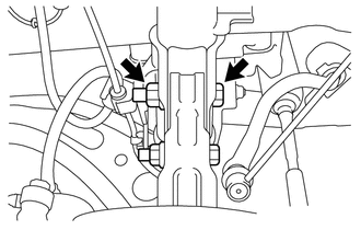
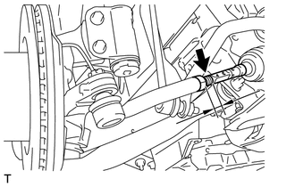
Loosen the lower mounting bolt and nut of the front shock absorber assembly and steering knuckle.
-
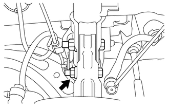
Replace the upper mounting bolt of the front shock absorber assembly and steering knuckle with a service bolt. (Part No.: SU003-02818)
Note
Insert the bolt from the rear side of the vehicle.
-
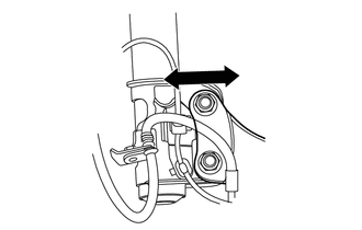
Pivot the lower mounting bolt to move the front shock absorber assembly and steering knuckle, and use the play between the bolt and bolt holds of the steering knuckle and front shock absorber assembly to adjust the camber.
Note
Left-right tolerance for camber is to be 0°45' (0.75°) or less.
Tech Tips
The range that can be adjusted by replacing bolts is 0°+/- 45' (0°+/- 0.75°).
-
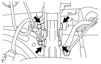
Tighten the 2 bolts and 2 new nuts.
- Torque:
- 155 N*m { 1581 kgf*cm, 114 ft.*lbf }
-
Install the front wheel.
- Torque:
- 120 N*m { 1224 kgf*cm, 89 ft.*lbf }
-
Lower the vehicle and bounce it up and down several times to stabilize the front suspension.
-
Check the camber.
-
Check the toe-in.
-
-
INSPECT TOE-IN
-
Bounce the vehicle up and down at the corners to stabilize the suspension.
-
Release the parking brake and move the shift lever to the neutral position (for manual transmission).
-
Release the parking brake and move the shift lever to N (for Automatic transmission).
-
Push the vehicle straight ahead approximately 5 m (16.4 ft.). (Step A)
-
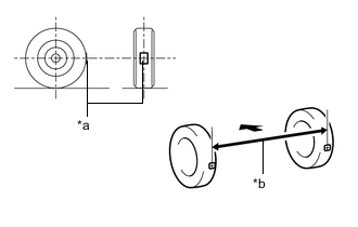
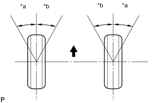
Text in Illustration *a Tread Center Mark *b Dimension B 
Front of the Vehicle Put tread center marks on the rearmost points of the front wheels and measure the distance between the marks (dimension B).
-
Slowly push the vehicle straight ahead to cause the front wheels to rotate 180°. Use the front tire valve as a reference point.
Tech Tips
Do not allow the wheels to rotate more than 180°. If the wheels rotate more than 180°, perform the procedure from Step A again.
-
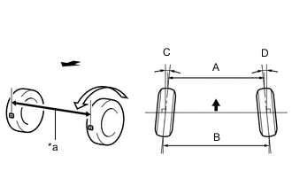
Text in Illustration *a Dimension A Front of the Vehicle Measure the distance between the tread center marks on the front side of the wheels (dimension A).
Standard Dimension (Unloaded Vehicle) Specified Condition C + D: 0°00' +/- 0°11' (0.00° +/- 0.19°) B - A: 0 +/- 3.0 mm (0 +/- 0.1181 in.) Tech Tips
Measure "B - A" only when "C + D" cannot be measured.
If the toe-in is not within the specified value, adjust it at the rack ends.
-
-
ADJUST TOE-IN
-
Measure the thread lengths of the right and left rack ends.
Standard Difference in thread length of 2.0 mm (0.0787 in.) or less -
Remove the rack boot set clips.
-
Loosen the tie rod end lock nuts.
-
Adjust the rack ends if the difference in thread length between the right and left rack ends is not within the specified range.
-
If the toe-in measurement is greater than the specified range (too much toe-out), extend the shorter rack end so that the length difference is within the specified range.
-
If the toe-in measurement is less than the specified range (too much toe-in), shorten the longer rack end so that the length difference is within the specified range.
-
Measure the toe-in.
-
-
Turn the right and left rack ends by an equal amount to adjust the toe-in.
-
Make sure that the thread lengths of the right and left rack ends are the same.
-
Tighten the tie rod end lock nuts.
- Torque:
- 85 N*m { 867 kgf*cm, 63 ft.*lbf }
-
Place the steering rack boots on the seats and install the steering rack boot clips.
Tech Tips
Make sure that the steering rack boots are not twisted.
-
-
INSPECT WHEEL ANGLE
-
Text in Illustration *a Inside *b Outside Front of the Vehicle Put tread center marks on the rearmost points of a turning radius gauge.
-
Turn the steering wheel fully to the left and right and measure the turning angle.
Tech Tips
Inspect while the vehicle is unloaded.
Wheel Turning Angle (Unloaded Vehicle) Inside Wheel
(Reference)
Outside Wheel
(Reference)
36°54'
(43.90°)
31°12'
(31.20°)
-
-
PLACE FRONT WHEELS FACING STRAIGHT AHEAD
-
VSC SENSOR NEUTRAL MEMORIZATION
-
HEIGHT CONTROL SENSOR SIGNAL INITIALIZE (w/ HID Headlight System)
-
ADJUST HEADLIGHT AIMING (w/ HID Headlight System)