PROPELLER SHAFT ASSEMBLY INSPECTION

PROCEDURE
-
INSPECT PROPELLER WITH CENTER BEARING SHAFT ASSEMBLY
-
Set the dial indicator so that the dial indicator measurement probe is centered on the propeller shaft with center bearing shaft assembly.
-
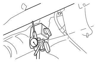
Lightly turn the propeller shaft with center bearing shaft assembly by hand, and measure the deflection.
Maximum runout 0.6 mm (0.0236 in.) Note
The dial indicator must be placed so that it is perpendicular to the propeller shaft with center bearing shaft assembly at the center of the shaft.
If the shaft runout is more than the maximum, replace the propeller shaft with center bearing shaft assembly.
-
-
INSPECT SPIDER BEARING
-
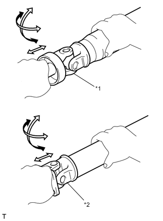
Text in Illustration *1 Front Spider Bearing *2 Rear Spider Bearing Check that the spider bearing rotates smoothly.
-
Check that there is no play in the spider bearing.
-
-
INSPECT CENTER SUPPORT BEARING ASSEMBLY
-
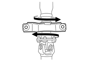
Turn the center support bearing assembly by hand. Check that the center support bearing assembly turns smoothly.
-
Check that the center support bracket of the center support bearing assembly is not cracked or deformed.
-
Check that the seals are not cracked or damaged.
Tech Tips
If the center support bearing assembly is damaged or worn, or does not turn smoothly, replace it.
-