MANUAL TRANSMISSION ASSEMBLY REMOVAL
PROCEDURE
-
DISCONNECT CABLE FROM NEGATIVE BATTERY TERMINAL
-
REMOVE NO. 1 ENGINE UNDER COVER
-
REMOVE NO. 2 ENGINE UNDER COVER
-
REMOVE REAR ENGINE UNDER COVER LH (w/ Floor Under Cover)
-
REMOVE REAR ENGINE UNDER COVER RH (w/ Floor Under Cover)
Tech Tips
Use the same procedure for the RH side as for the LH side.
-
DRAIN MANUAL TRANSMISSION OIL
-
REMOVE PROPELLER SHAFT WITH CENTER BEARING ASSEMBLY
-
REMOVE FRONT STABILIZER BAR
-
REMOVE STARTER ASSEMBLY
-
SEPARATE WIRE HARNESS
Tech Tips
Fix the disconnected harness components with tape to keep them out of the way.
-
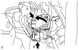
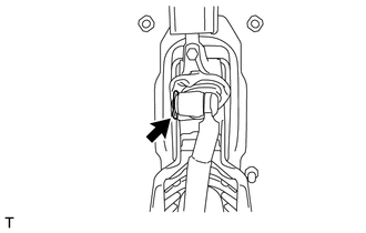
Release the lock of connector (A) and disconnect the connector.
-
Disconnect the connector (B).
-
Disconnect the 2 connectors.
-
Remove the bolt and disconnect the ground cable.
-
Disengage the wire harness clamp.
-
Remove the bolt and the wire harness clamp bracket.
-
-
SEPARATE CLUTCH RELEASE CYLINDER ASSEMBLY
-
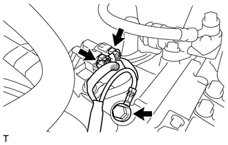
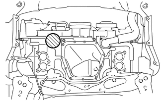
Remove the 2 bolts and separate the clutch release cylinder assembly.
-
-
SEPARATE MANUAL TRANSMISSION ASSEMBLY
-
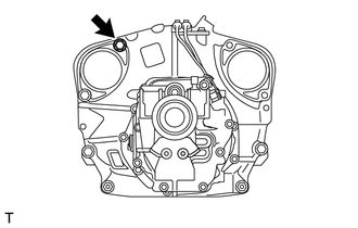
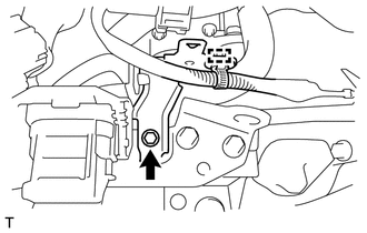
Remove the bolt from the manual transmission assembly.
-
-
REMOVE EXHAUST MANIFOLD
-
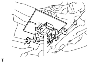
SUPPORT ENGINE ASSEMBLY
-
Support the engine assembly with an engine lifter so that it is stable, as shown in the illustration.
Text in Illustration 
Attachment Placement Positions Note
-
Set the engine assembly with transmission so that it is horizontal.
-
Never attach the attachment and plate lift attachment to the oil pan section of the engine assembly.
-
-
-
DISCONNECT FLOOR SHIFT LEVER ASSEMBLY
-
Turn over the shift and select lever boot.
-
Using a screwdriver, remove the clip and the floor shift lever assembly.
-
Remove the plate washer from the floor shift lever assembly.
-
Remove the 2 bushings and O-ring from the floor shift lever assembly.
-
-
REMOVE EXHAUST PIPE BRACKET
-
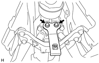
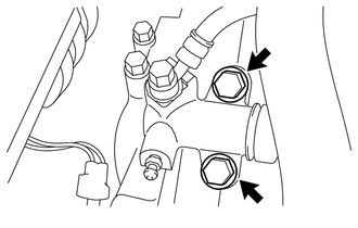
Remove the 2 bolts and the exhaust pipe bracket.
-
-
SUPPORT MANUAL TRANSMISSION ASSEMBLY
-
Support the manual transmission assembly with a transmission jack.
Note
-
Check that the manual transmission assembly is centered on the transmission jack plate.
-
When removing the manual transmission assembly, support the engine assembly so that it does not tilt.
-
-
-
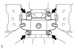
REMOVE REAR NO. 2 ENGINE MOUNTING INSULATOR
-
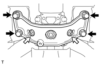
Remove the 4 bolts, 2 washers, 2 nuts and rear No. 2 engine mounting insulator.
Text in Illustration 
Bolt 
Nut
-
-
DISCONNECT FLOOR SHIFT CONTROL SHIFT LEVER RETAINER
-
Tilt the manual transmission assembly.
-
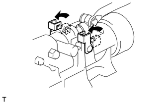
Pull up the locks of the shift lever pins, and remove the 2 shift lever pins.
-
Disconnect the floor shift control shift lever retainer.
-
-
REMOVE SHIFT AND SELECT LEVER BOOT
-
Remove the shift and select lever boot from the floor shift lever assembly.
-
-
REMOVE MANUAL TRANSMISSION ASSEMBLY
-
Remove the 3 bolts, 2 nuts and manual transmission assembly.
Text in Illustration Bolt Nut Note
-
Do not apply excessive force to the transmission assembly as this will break the input shaft.
-
To prevent damage to the knock pins, do not pry between the manual transmission assembly and the engine assembly.
-
-
-
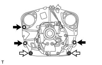
REMOVE REAR NO. 1 ENGINE MOUNTING INSULATOR
-
Remove the 4 bolts and rear No. 1 engine mounting insulator.
-
-
REMOVE FLOOR SHIFT CONTROL SHAFT
-
REMOVE CONTROL SHAFT