CLUTCH PEDAL SWITCH(for LHD) INSTALLATION
PROCEDURE
-
INSTALL CLUTCH START SWITCH ASSEMBLY
-
Install the clutch start switch assembly to the clutch pedal support sub-assembly with the nut.
- Torque:
- 8.0 N*m { 82 kgf*cm, 71 in.*lbf }
-
Connect the clutch start switch connector.
-
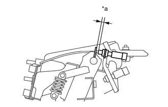
Text in Illustration *a Clearance With the clutch pedal fully depressed, check that the clearance shown in the illustration is as specified.
Standard clearance 3.5 to 4.0 mm (0.138 to 0.157n.) Tech Tips
Do not turn the clutch start switch assembly.
-
-
INSTALL CLUTCH PEDAL SUPPORT SUB-ASSEMBLY
-
INSTALL CLUTCH SWITCH ASSEMBLY
-
Install the clutch switch assembly to the clutch pedal support sub-assembly with the nut.
- Torque:
- 8.0 N*m { 82 kgf*cm, 71 in.*lbf }
-
Connect the clutch switch connector.
-
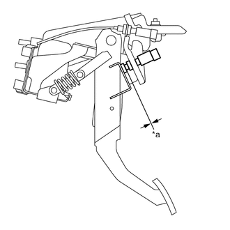
Text in Illustration *a No Clearance Without depressing the clutch pedal, check that there is no clearance between the switch shaft and the clutch pedal stopper.
Tech Tips
Do not turn the clutch switch assembly.
-
-
INSTALL LOWER NO. 1 INSTRUMENT PANEL AIRBAG ASSEMBLY (w/ Knee Airbag)
-
INSTALL NO. 1 INSTRUMENT PANEL UNDER COVER SUB-ASSEMBLY (w/o Knee Airbag)
-
INSTALL INSTRUMENT SIDE PANEL LH (w/o Knee Airbag)
-
CONNECT CABLE TO NEGATIVE BATTERY TERMINAL
-
INSPECT CLUTCH START SYSTEM