CLUTCH UNIT INSPECTION

PROCEDURE
-
INSPECT CLUTCH DISC ASSEMBLY
-
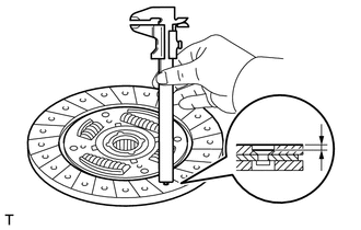
Using a vernier caliper, measure the rivet head depth.
Minimum rivet depth 0.3 mm (0.0118 in.) If necessary, replace the clutch disc assembly.
-

Install the clutch disc assembly to the manual transmission assembly.
Note
Insert the clutch disc assembly in the correct direction.
-
Using a dial indicator with a roller instrument, measure the clutch disc assembly runout.
Maximum runout 0.8 mm (0.0315 in.) If necessary, replace the clutch disc assembly.
-
-
INSPECT CLUTCH COVER ASSEMBLY
-
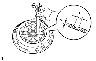
Using a vernier caliper, measure the depth and width of the diaphragm spring wear.
Maximum A (Depth) 0.5 mm (0.0197 in.) B (Width) 6.0 mm (0.236 in.) If necessary, replace the clutch cover assembly.
-
-
INSPECT FLYWHEEL SUB-ASSEMBLY
-
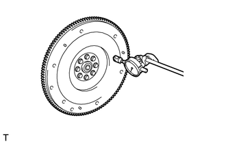
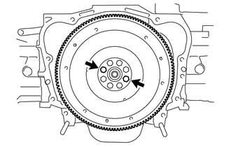
Using a dial indicator, measure the flywheel sub-assembly runout.
Maximum runout 0.1 mm (0.00394 in.) If necessary, replace the flywheel sub-assembly.
-
-
INSPECT CLUTCH RELEASE BEARING ASSEMBLY
-
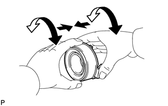
Check that the clutch release bearing assembly moves smoothly without abnormal resistance by turning the sliding parts of the clutch release bearing assembly (contact surfaces with the clutch cover) while applying force in the axial direction.
-
Inspect the clutch release bearing assembly for damage and wear.
If necessary, replace the clutch release bearing assembly.
-
-
INSPECT FLYWHEEL BEARING
-
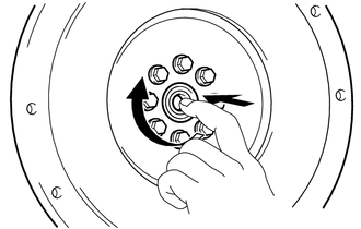
Turn the flywheel bearing by hand while applying rotational force and check that the flywheel bearing rotates smoothly. If the flywheel bearing sticks or a considerable amount of resistance is felt, replace the flywheel bearing.
Tech Tips
The flywheel bearing is permanently lubricated and requires no cleaning or lubrication.
-
-
REPLACE FLYWHEEL BEARING
-
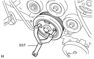
Using SST, hold the crankshaft pulley.
- SST
- 09960-10010 ( 09962-01000, 09963-01000 )
-
Remove any 2 diametrically opposite bolts.
-
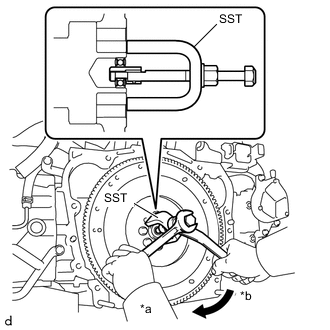
Text in Illustration *a Hold *b Turn Using SST, remove the flywheel bearing.
- SST
- 09303-35011
-
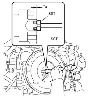
Text in Illustration *a Depth from flywheel edge Using SST and a hammer, tap in a new flywheel bearing.
- SST
- 09950-60010 ( 09951-00340 )
- 09950-70010 ( 09951-07150 )
Standard depth 0 to 0.4 mm (0 to 0.0158 in.) Note
-
Do not tap in the flywheel bearing at an angle.
-
Do not tap in the flywheel bearing more than necessary.
Tech Tips
After installing the flywheel bearing, make sure that it rotates smoothly.
-
Using SST, hold the crankshaft pulley.
- SST
- 09960-10010 ( 09962-01000, 09963-01000 )
-
Install the 2 bolts.
- Torque:
- 85 N*m { 867 kgf*cm, 63 ft.*lbf }
-