CLUTCH UNIT INSTALLATION

PROCEDURE
-
INSTALL CLUTCH DISC ASSEMBLY
-
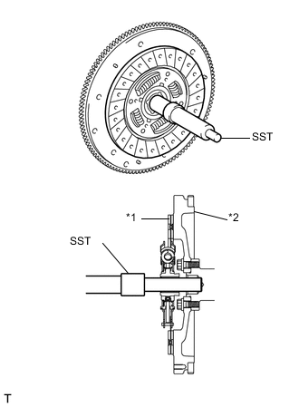
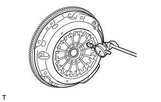
Text in Illustration *1 Clutch Disc Assembly *2 Flywheel Sub-assembly Insert SST into the clutch disc assembly, and then insert them both into the flywheel sub-assembly.
- SST
- 09301-00110
Note
Insert the clutch disc assembly in the correct direction.
-
-
INSTALL CLUTCH COVER ASSEMBLY
-
Reuse the flywheel sub-assembly and clutch cover assembly:
-
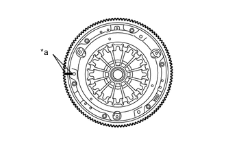
Text in Illustration *a Matchmark Align the matchmark on the clutch cover assembly with that on the flywheel sub-assembly.
-
-
Replace the flywheel sub-assembly or clutch cover assembly:
-
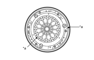
Text in Illustration *a Unbalance Mark Position the clutch cover assembly so that there is a gap of at least 120° between the unbalance marks on the flywheel sub-assembly and the clutch cover assembly.
-
-
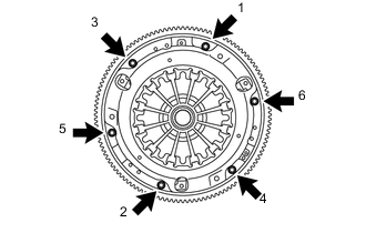
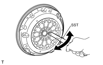
Following the procedures shown in the illustration, tighten the 6 bolts in order, starting with the bolt located near the knock pin at the top.
- SST
- 09301-00110
- Torque:
- 16 N*m { 163 kgf*cm, 12 ft.*lbf }
Tech Tips
-
Following the order in the illustration, tighten the bolts evenly one at a time.
-
Move SST up, down, right and left lightly after checking that the disc is in the center, and tighten the bolts.
-
-
INSPECT AND ADJUST CLUTCH COVER ASSEMBLY
-
Using a dial indicator with a roller instrument, measure the diaphragm spring tip alignment.
Maximum non-alignment 0.5 mm (0.0197 in.) -
If the alignment is not as specified, using SST, adjust the diaphragm spring tip alignment.
- SST
- 09333-00013
-
-
INSTALL RELEASE FORK SUPPORT
-
Install the release fork support to the manual transmission assembly.
- Torque:
- 16 N*m { 163 kgf*cm, 12 ft.*lbf }
-
-
INSTALL CLUTCH RELEASE FORK BOOT
-
Install the clutch release fork boot to the manual transmission assembly.
-
-
INSTALL RELEASE BEARING HUB CLIP
-
Install the 3 release bearing hub clips to the clutch release bearing assembly.
-
Install the release bearing hub clip to the clutch release fork sub-assembly.
-
-
INSTALL CLUTCH RELEASE FORK SUB-ASSEMBLY
-
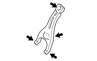
Apply release hub grease to the contact surfaces of the clutch release fork sub-assembly and clutch release bearing assembly, clutch release fork sub-assembly and clutch release cylinder push rod, and clutch release fork sub-assembly and release fork support.
Text in Illustration 
Release Hub Grease Grease Toyota Genuine Release Hub Grease or equivalent -
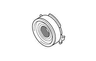
Apply release hub grease to the clutch release bearing assembly as shown in the illustration.
Text in Illustration 
Release Hub Grease Grease Toyota Genuine Release Hub Grease or equivalent -
Engage the 2 release bearing hub clips and install the clutch release fork sub-assembly to the clutch release bearing assembly.
-
-
INSTALL CLUTCH RELEASE BEARING ASSEMBLY
-
Install the clutch release bearing assembly with the clutch release fork sub-assembly to the manual transmission assembly.
Note
After the installation, move the fork forward and backward to check that the release bearing slides smoothly.
-
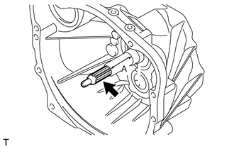
Apply clutch spline grease to the input shaft spline.
Text in Illustration Clutch Spline Grease Grease Toyota Genuine Clutch Spline Grease or equivalent Note
Do not apply grease to portion A shown in the illustration.
-
-
INSTALL MANUAL TRANSMISSION ASSEMBLY