CLUTCH PEDAL(for LHD) INSTALLATION
PROCEDURE
-
INSTALL CLUTCH PEDAL PAD
-
Install the clutch pedal pad to the clutch pedal sub-assembly.
-
-
INSTALL NO. 1 CLUTCH PEDAL CUSHION
-
Install the No. 1 clutch pedal cushion to the clutch pedal sub-assembly.
-
-
INSTALL CLUTCH PEDAL STOPPER
-
Install the clutch pedal stopper to the clutch pedal support sub-assembly.
-
-
INSTALL CLUTCH PEDAL SUB-ASSEMBLY
-
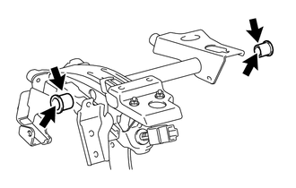
Apply MP grease to the 2 clutch pedal bushes.
Text in Illustration 
MP grease -
Install the clutch pedal sub-assembly and 2 clutch pedal bushes to the clutch pedal support sub-assembly.
-
Using a pin punch (3 mm (0.118 in.)) and a hammer, align the clutch pedal lever sub-assembly hole and the clutch pedal sub-assembly hole, and insert the straight pin from above.
-
-
INSTALL CLUTCH PEDAL SPRING
-
Install the 2 bushes to the clutch pedal sub-assembly and clutch pedal support sub-assembly.
-
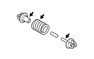
Apply MP grease to the assist rod A, assist rod B and clutch pedal spring.
Text in Illustration MP grease -
Install the assist rod A, assist rod B, clutch pedal spring and assist bush to the clutch pedal sub-assembly and the clutch pedal support sub-assembly.
-
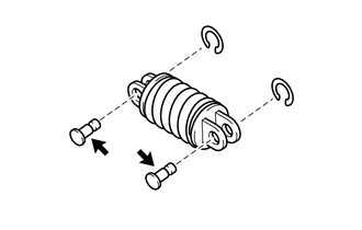
Apply MP grease to the 2 clevis pins.
Text in Illustration MP grease -
Install the 2 clevis pins and 2 E-rings.
Tech Tips
Install the clevis pin from the left side of the vehicle.
-
-
INSTALL CLUTCH SWITCH ASSEMBLY
-
Install the clutch switch assembly to the clutch pedal support sub-assembly with the nut.
- Torque:
- 8.0 N*m { 82 kgf*cm, 71 in.*lbf }
-
-
INSTALL CLUTCH START SWITCH ASSEMBLY
-
INSTALL CLUTCH PEDAL SUPPORT SUB-ASSEMBLY
-
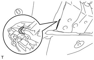
Text in Illustration *1 Hook Insert the hook on the clutch pedal support sub-assembly into the vehicle panel.
-
Install the clutch pedal support sub-assembly to the vehicle with the 4 nuts and 3 bolts.
- Torque:
- 18 N*m { 184 kgf*cm, 13 ft.*lbf }
-
Install the clutch master cylinder assembly with the 2 nuts.
- Torque:
- 18 N*m { 184 kgf*cm, 13 ft.*lbf }
-
Apply MP grease to the new clevis pin.
-
Install the clutch master cylinder push rod clevis to the clutch pedal lever sub-assembly with the clevis pin and a clip.
Tech Tips
Install the clevis pin from the left side of the vehicle.
-
Apply MP grease to the push rod pin.
-
Install the brake master cylinder push rod clevis with the push rod pin and a clip.
Tech Tips
Install the push rod pin from the left side of the vehicle.
-
Connect the connector and engage the wire harness clamp.
-
Connect the 3 connectors.
-
-
INSTALL STEERING INTERMEDIATE SHAFT ASSEMBLY
-
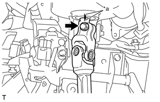
Text in Illustration *a Matchmark Install the steering intermediate shaft assembly to the steering column assembly.
Note
Align the matchmarks on the steering intermediate shaft assembly and the steering column assembly.
-
Install the bolt.
- Torque:
- 35 N*m { 357 kgf*cm, 26 ft.*lbf }
-
-
INSPECT AND ADJUST CLUTCH PEDAL
-
INSPECT CLUTCH SWITCH ASSEMBLY
-
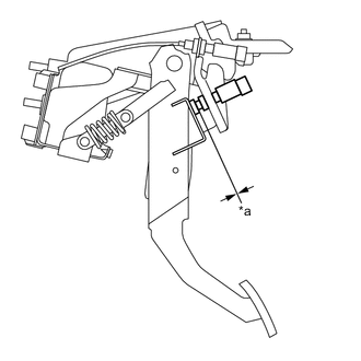
Text in Illustration *a No Clearance Without depressing the clutch pedal sub-assembly, check that there is no clearance between the clutch switch shaft and the clutch pedal stopper.
-
-
INSTALL STEERING CONTROL ECU
-
INSPECT CLUTCH START SYSTEM